Upload Ground Control Points (GCPs)
1. Description
This article will describe the benefits of GCP and the GCP upload procedure in Aether.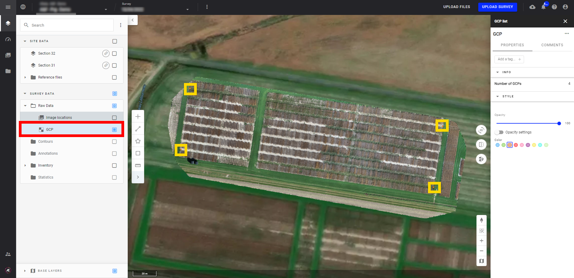
2. Reason for using GCPs
In order to ensure the highest accuracy processing possible, even in RTK/PPK situations, one or more GCPs are recommended.
For this reason, during Standard Processing, the system will expect a GCP file even in RTK/PPK situations.
Alteia recommends following this protocol, if no GCPs are available you may upload our GCP_Recommendation.txt file.
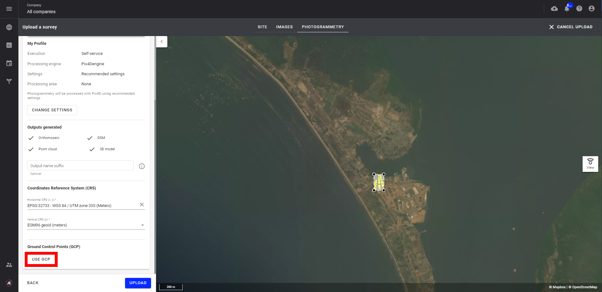
- Select "USE GCP" during a new upload process. With a Self-service execution of photogrammetry selected, the user will have to click the GCPs during the next steps.
- Selecting both the Advanced photogrammetry & USE GCP options will alternatively result in the user not clicking the GCPs and having it managed by Alteia teams.
3. GCP Upload
Drag & drop your GCP file in the dedicated area or press Browse file to select the file manually.
The file should be in .CSV or .TXT format, no header row and only delimited with a comma (“ , ”)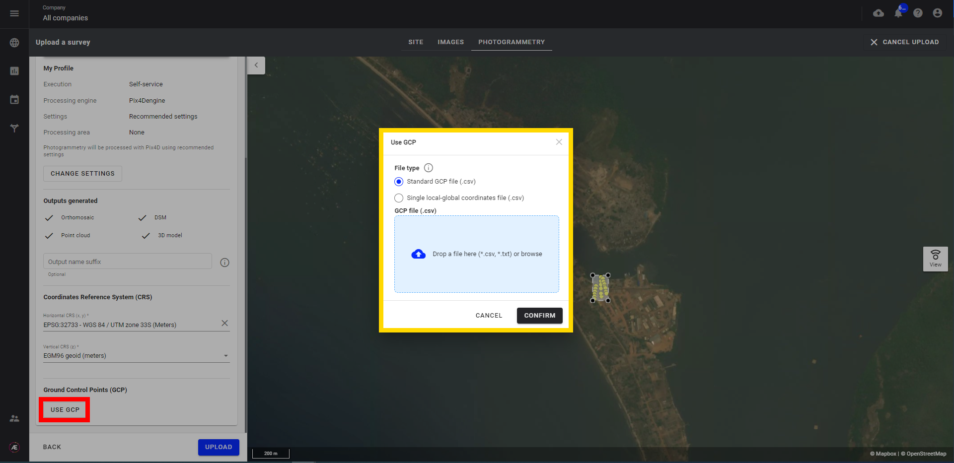 The file must be in the following format:
- Name/reference of the GCP
- X coordinate
- Y coordinate
- Z value
- X accuracy (optional)
- Y accuracy (optional)
Find below an example of a GCP file:
Once the GCP file has been uploaded, verify that the x/y/z columns appear in the correct order.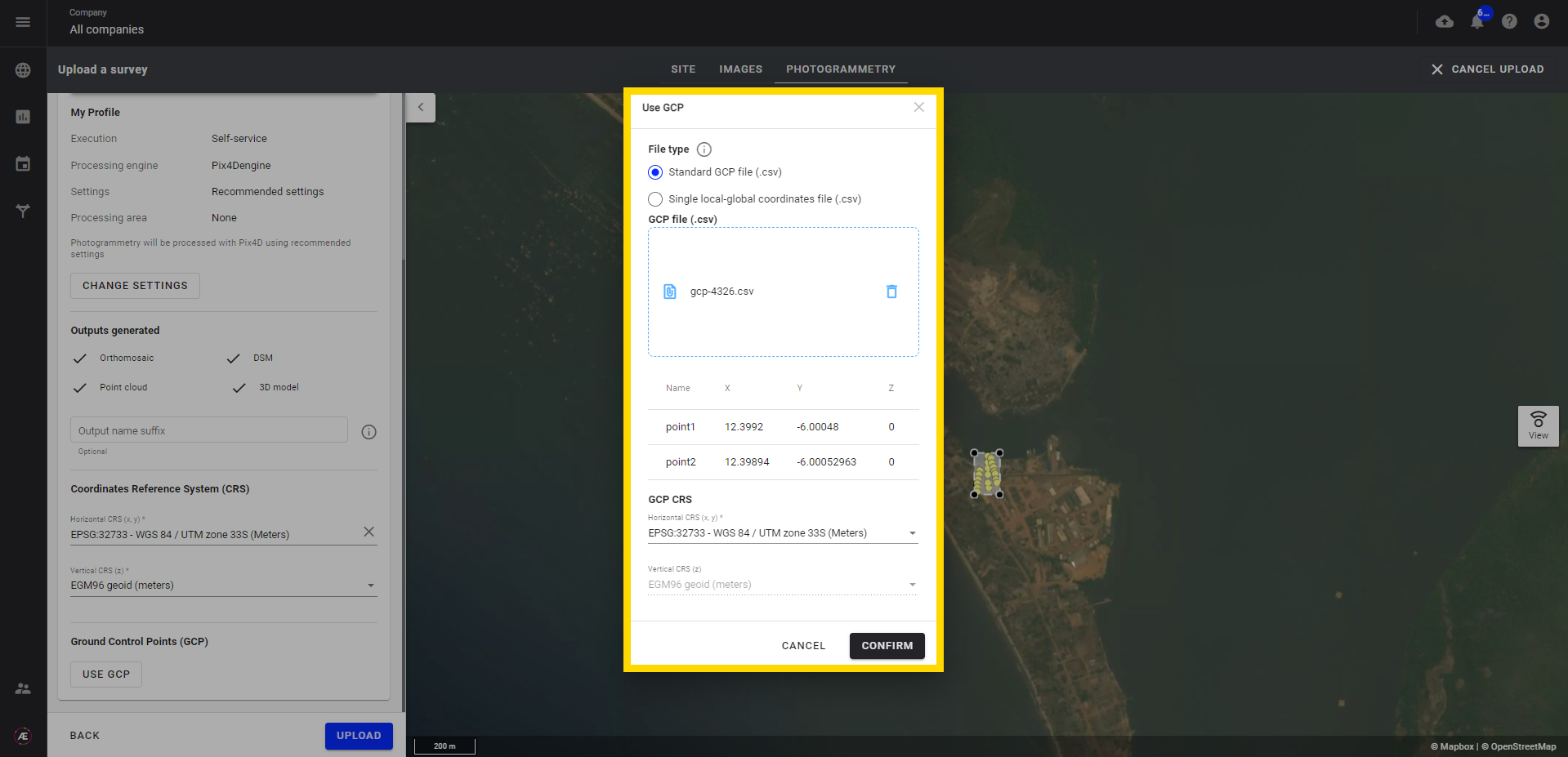
Press Edit CRS to select the projection of the GCPs. The GCP CRS must be selected and must match the project CRS. If it is not the same, reconvert the GCP file to the Project CRS. If the selected CRS & GCP file coordinate system match, the GCPs should appear on the map as orange dots within the survey boundary.
If nothing appears, then it may be possible that the CRS is incorrect or the X and Y coordinates are reversed.
To retry, deselect Add ground control points (GCP), fix the file, and then reselect Add ground control points (GCP) and try again.
4. GCP Tagging
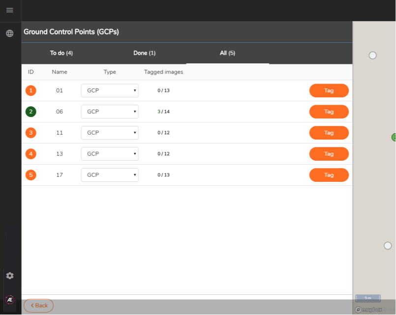
When you enter the GCP tagging interface, the uploaded GCPs will be listed on the left side of the window and corresponding orange dots will appear on the right side map background:
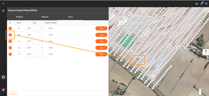
Please note that you have the option at this step to define the target as a plain Check Point instead of a Ground Control Point, i.e. utilized in absolute accuracy estimation of the model instead of being used for georeferencing in the photogrammetry processing :
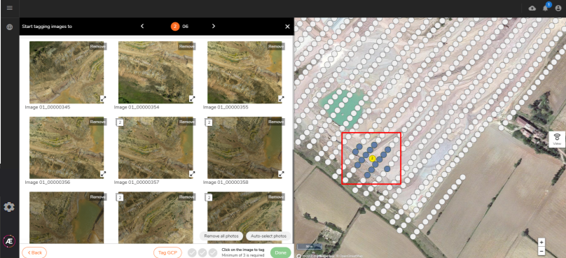
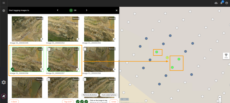
Clicking on a GCP (on the map) will select its neighboring images (now in dark grey) and display them in a gallery :

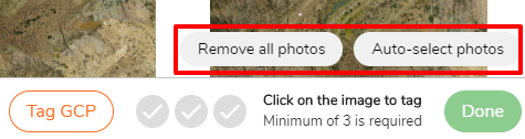
You can choose to unselect these images if necessary in the bottom section of this gallery:
Proceed to GCP tagging per image tagging: a green cross marks the clicked position:
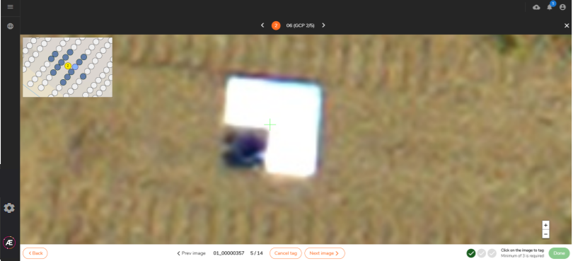
Green dots indicate tagged images; a minimum of 3 images is required per GCP :

In the GCP tagging gallery, GCP-tagged pictures will equally be highlighted by a green frame:
Press the Back button to read GCP tagging status list:
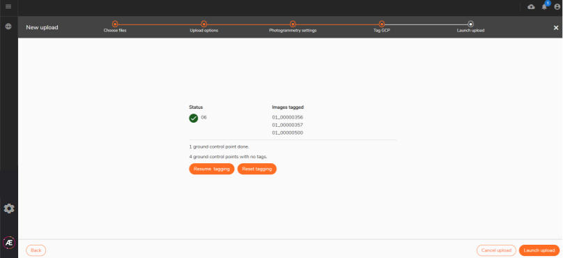
Continue your tagging process if necessary. Once you’ve finished, press Back again from the tagging status list to go back to the Launch upload step:
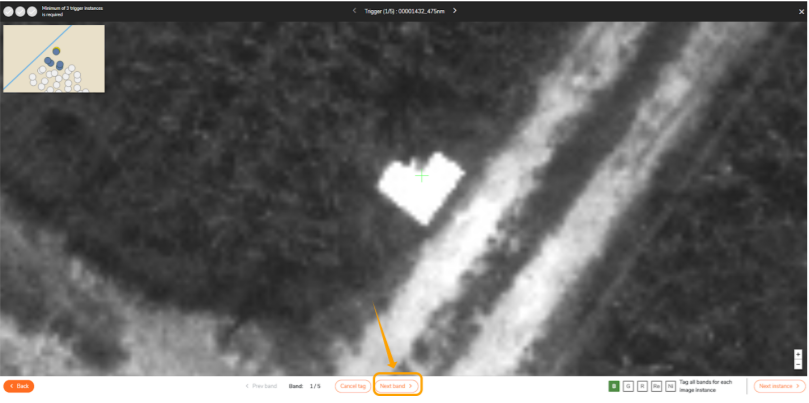
Make sure to click on "Next Band " to tag every band of the datasets.
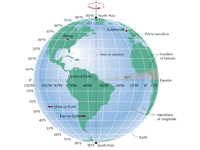
5. About Coordinates
- Eastings would be X
- Northings would be Y
- X field would be Longitude
- Y field would be Latitude
- Longitude is W or E
- Latitude is N or S