3D Viewer
Discover our powerful 3D viewer and all its functionalities !
1. Description
Aether's 3D viewer allows a user to visualize a large 3-dimensional (3D) Model for a given project that has been processed via the photogrammetry analytic within the platform or uploaded on the platform from external software.
This article aims to highlight the 3D viewer features and tools.
Limitations
- Only triangulated 3D models are supported
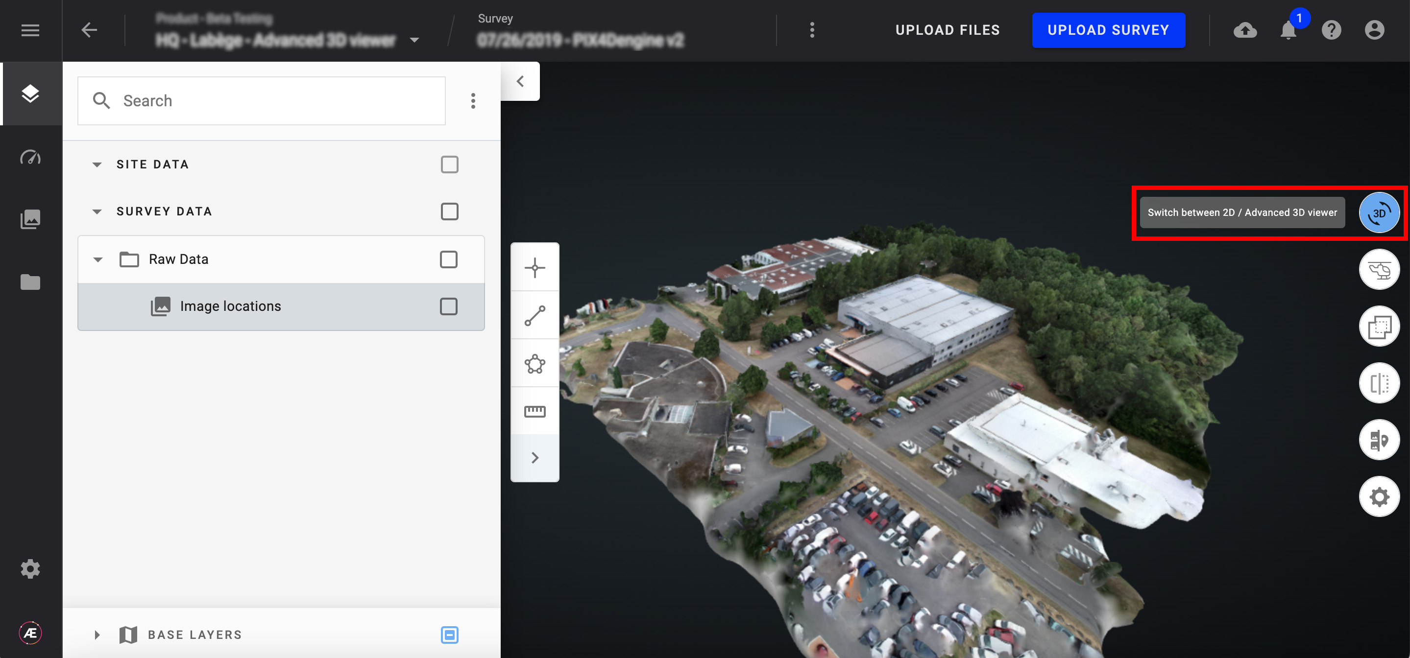
2. Switching between 2D / 3D viewer
Click on "Switch between 2D / 3D viewer" button on the map view to display the 3D project view. Click on the same button to return to the 2D view.
When switching from 2D to 3D, a loading bar appears at the bottom of the screen, indicating that 3D layers (PCL or MESH) are loading.
3. Advanced 3D Viewer tools
3.1. Split View: Gallery/3D and proximity filter
Known limitations
- The “proximity filter” is not compatible with Metashape photogrammetry outputs generated before R2410.
- By clicking on the "Split screen to view images" button, the Gallery mode is activated, splitting the screen to visualize the original images associated with the 3D data.
- When opening the “Split view”, the “image locations” layer is not displayed by default anymore. This layer can be activated in the layer panel, in the group “Raw Data”.
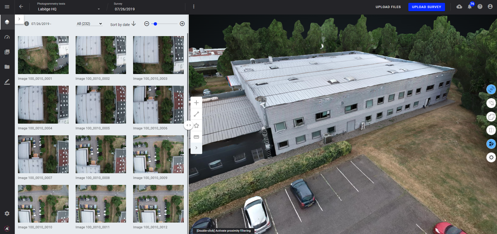
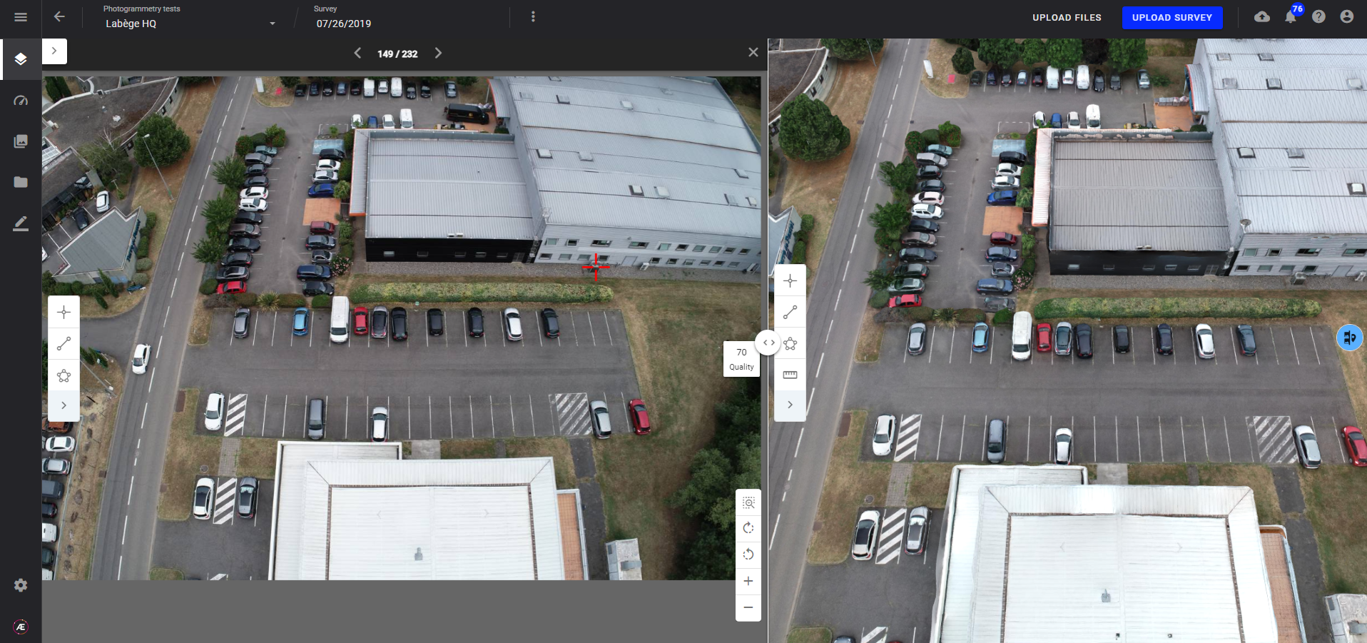
- Once “Split view” opened, you can activate the “proximity filter” :
- By double-clicking on any point of the 3D view:
- A red cross appears on the 3D model, and the gallery of images is filtered to display only images that can see the clicked point.
- A red cross appears on images at the position of the clicked point.
- The “image locations” layer is automatically displayed, filtering the positions of images not viewing the clicked point.
- The drop down menu on top of the gallery indicates “Proximity”, with the number of filtered photos.
- By double-clicking on an annotation in the 3D view:
- The “image locations” layer is automatically displayed, filtering the positions of images not viewing the clicked annotation.
- The drop down menu on top of the gallery indicates “Proximity”, with the number of filtered photos.
- By double-clicking on any point of the 3D view:


- To deactivate the “proximity filter” mode : select “All” in the drop down menu on top of the gallery, or close the split view.
3.2. Split view - Image and 3D viewer
Once split view is opened, the user can open images by clicking on the arrows on the top left of an image:
The image is opened in the left menu, and the model 3D is automatically oriented and zoomed to see the same field of view as the image.
From there, the user can create annotations either on the image or on the 3D model.
Image annotations vs 3D annotations
There are several types of annotations : images annotations (available on images only), 2D annotations (only visible in the 2D viewer) and 3D annotations.
For 3D annotations, there is an option that enable users to project 3D annotations on images. This option is very useful for 3D asset inspection, because annotations can be created on images and automatically projected in 3D and on other images, avoiding the duplication of anomalies on several images.
Please refer to 3D annotations article to get more details on this function.
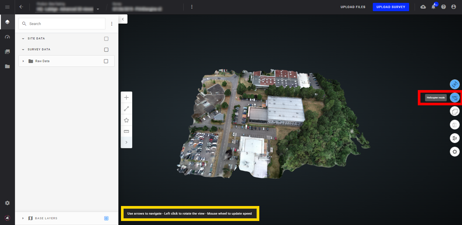
3.3. Helicopter mode
The Helicopter mode simulates helicopter navigation over the project using the keyboard's arrows for direction and the mouse wheel to manage the speed.
3.4. Compare tools
Compare tools are available in the 3D viewer, for more information see Compare View.

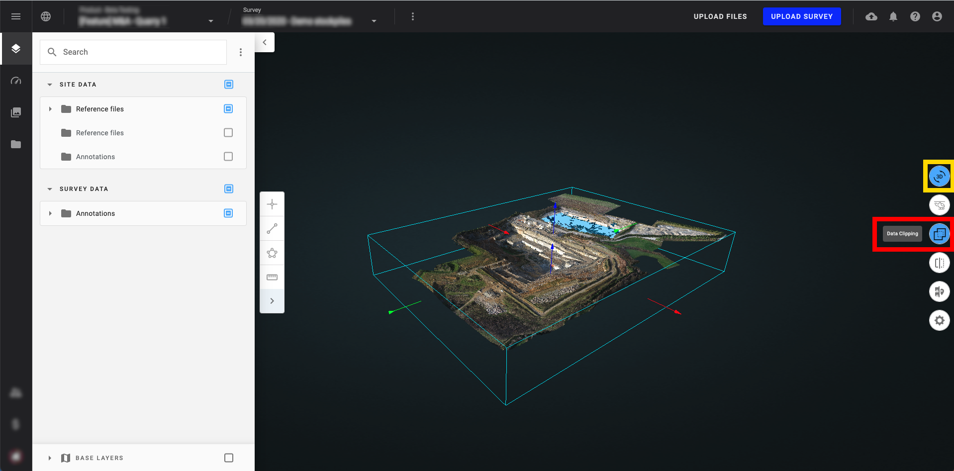
3.5. Data Clipping Tool
The Data Clipping tool allows the user to manipulate a bounding box in 3 axes resulting in a data visibility filter. As the user adjusts the bounding box extent, only the data within the clipping box remains visible while data outside the clipping box is not visible. Toggling the Data Clipping tool off returns the 3D file or files back to their full visible extents.
Info
It is the first version of this tool and there are some limitations:
- You can't annotate or measure something while this tool is enabled
- You can't move the clip box center
- You can't save a clipped model
Let us know how you plan to use this tool!
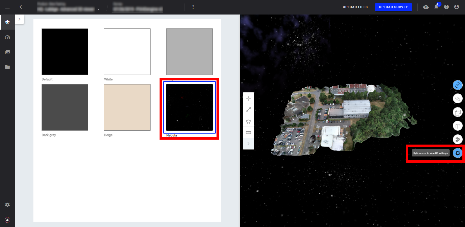
3.6 3D viewer settings
Click on the "Split screen to view 3D settings" to change the background of the 3D view.
4. Layers Panel
4.1. Enabling & Disabling the 3D Layers
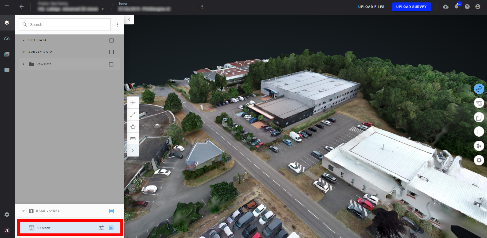
Select layers to be displayed from the “Base Layers” section in the bottom part of the left panel.
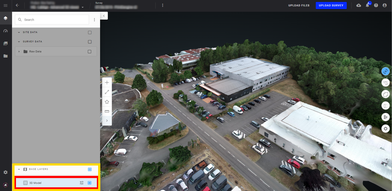
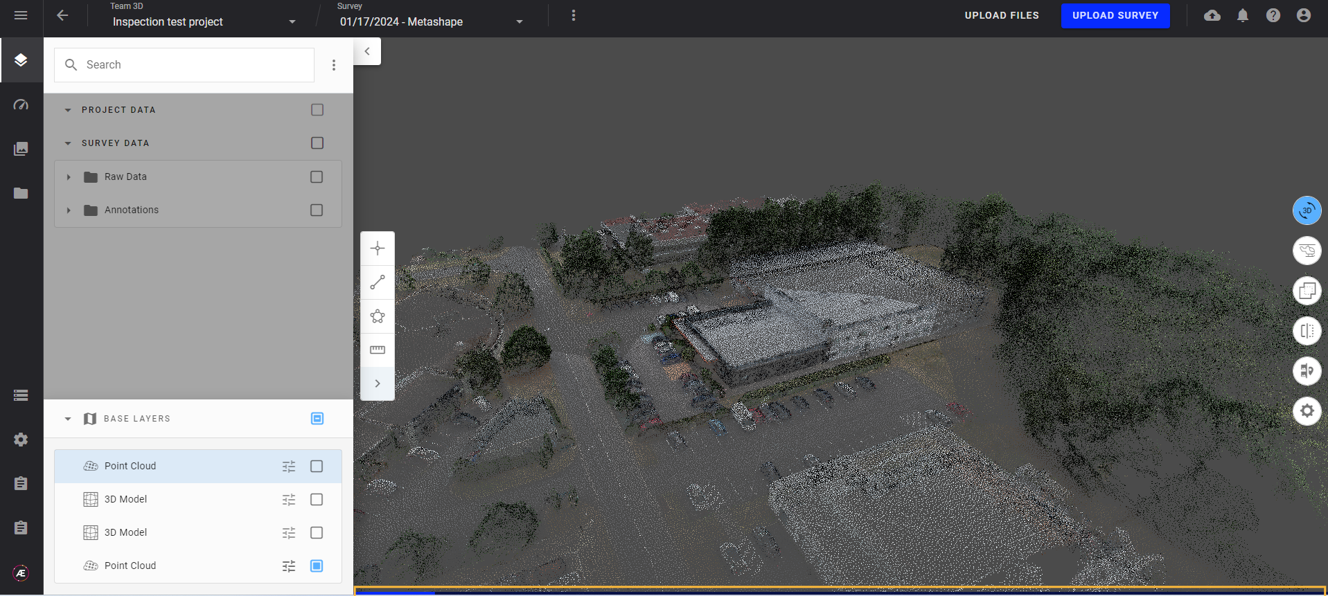
4.2. 3D Models
- Within the 3D view, switch between available 3D items from the "BASE LAYERS" section.
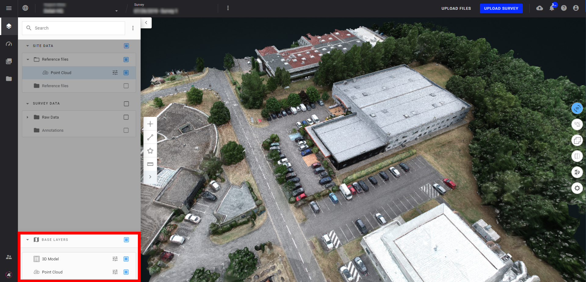
- Point Cloud

- 3D Model
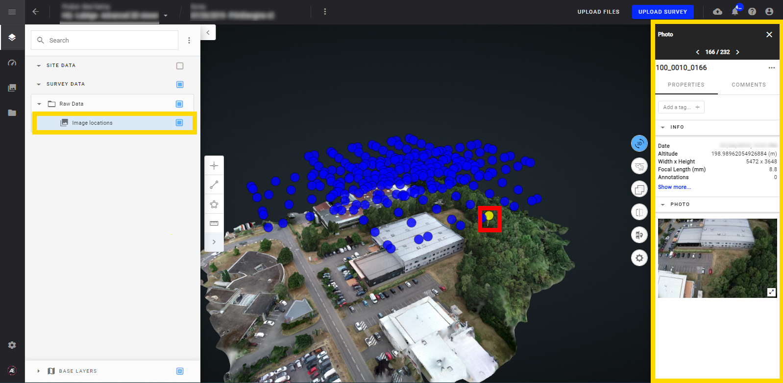
4.3. Single image locations in 3D View
From the Layer Panel, selecting Image Locations will cause the image positions to be displayed as points in the 3D view. Clicking on any of these markers will open a single image in the information panel on the right side.
There are 2 types of location markers:
- The electric blue location marker where the photogrammetry process has been done results in the pyramid projection of the picture.
- The dark blue location marker where there is no photogrammetry process launched results in just the picture location and preview.
Selected image is displayed in yellow.
5. Measure & annotation
For annotation on 3D view see Annotation Creation and Edition ;
For 3D measuring see Measurement Tool.
6. Style options
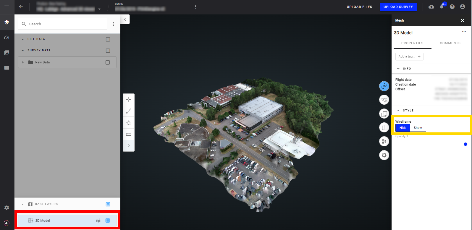
6.1. 3D model style options
With a 3D mesh model, display or hide the wireframe from the Style section of the model information panel.
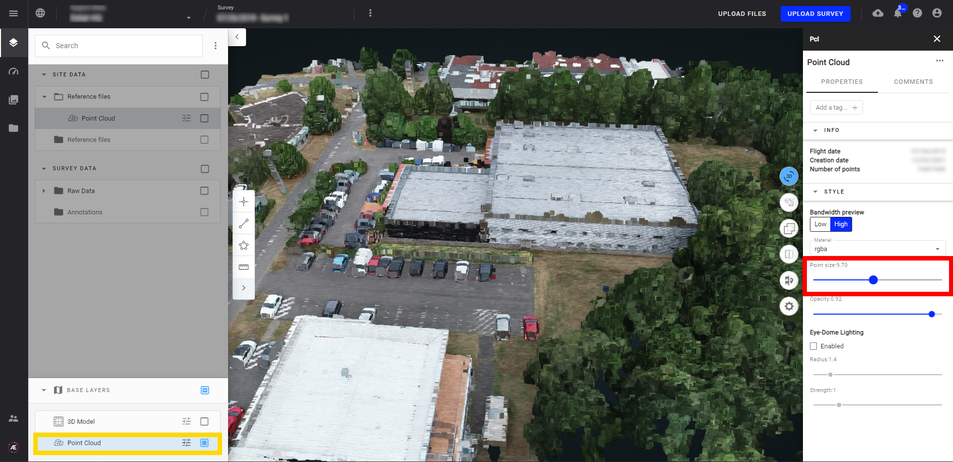
6.2. Point cloud style options
On the "BASE LAYERS" menu, display the "Point Cloud" layer and click on this layer to open the menu.
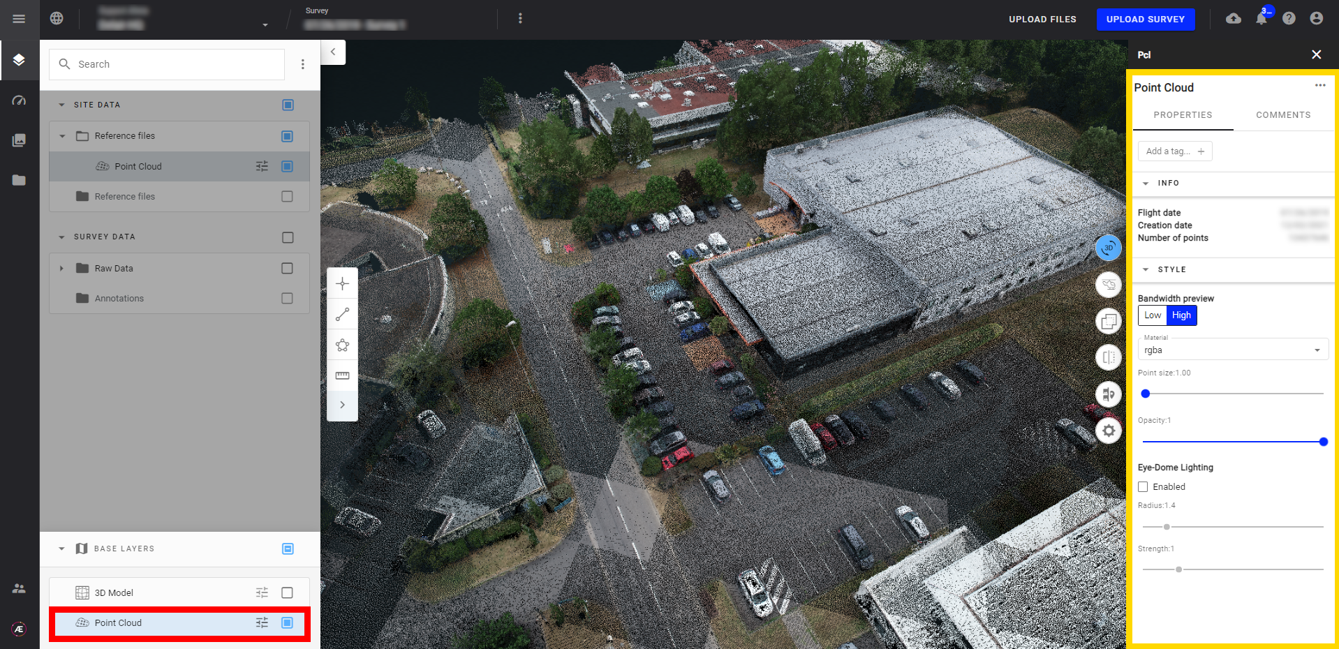
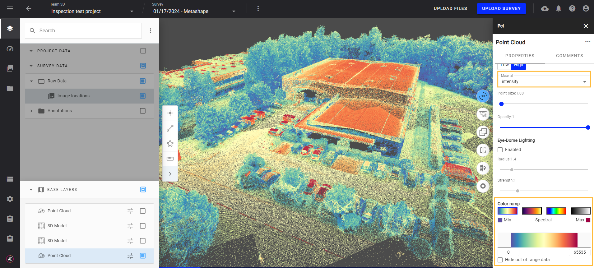
6.2.1. Material
With material, change visualization type (classification, elevation, intensity… and even your material).
Example 1: Classification
- To see the classified point clouds:
- Select the point cloud layer (visible in 3D Viewer) and click on it to open the right panel info. In the right panel info, section "Bandwidth preview", choose "classification" from the menu "Material"
- Scroll down the right panel info to see the "CLASSIFICATION" section and the legend for each classified class.
- Tick/untick a class to show/hide this class from the viewer.
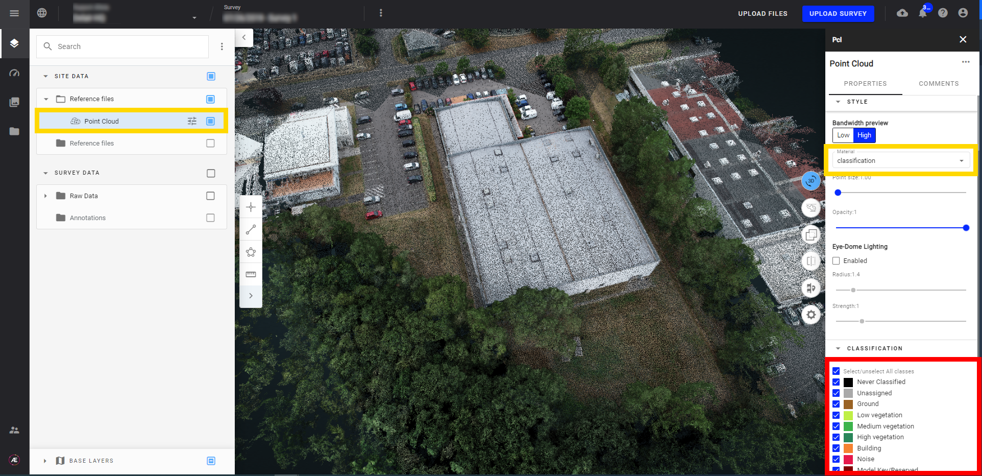
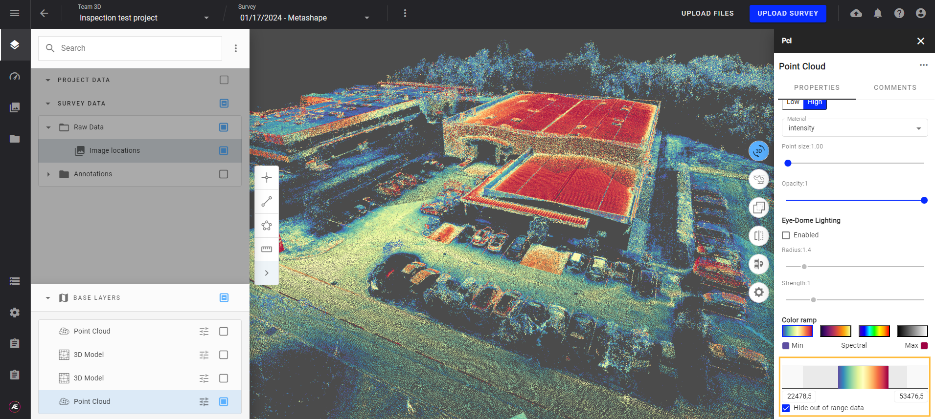
- Selecting any other material than classification allows the user to apply a colour ramp to the point cloud, according to the values of the selected material.
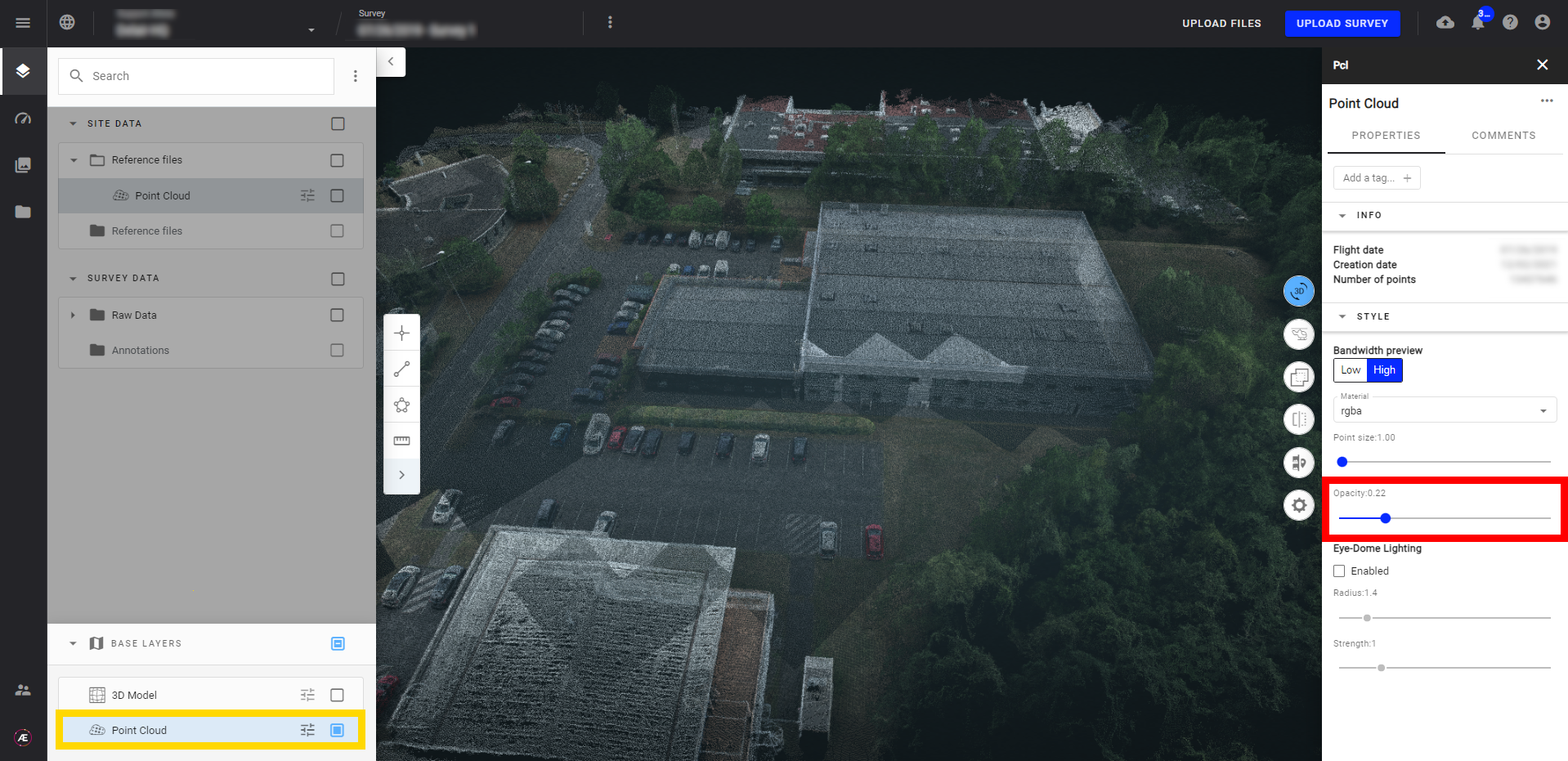
Change the opacity by moving the cursor.
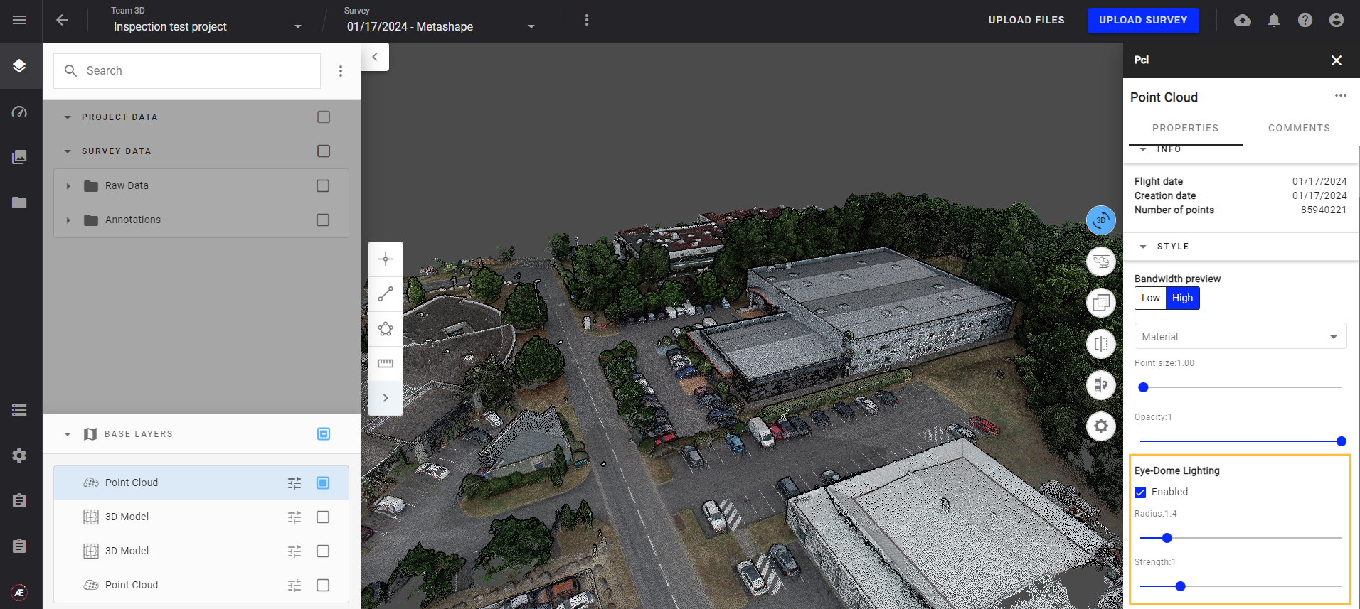
6.2.3. Eye-Dome Lighting
Enable the Eye-Dome Lightning (EDL) to adjust the Radius and Strength to accentuate the shapes of objects within the Point Cloud.