

Annotation Creation and Edition
Learn how to create and edit annotations with ease in this comprehensive guide, from understanding the different types of annotations to mastering the process of adding and modifying them within various content formats.
1. Description
Image annotation serves as a fundamental component in both 2D and 3D views, offering a versatile tool for highlighting and marking specific aspects of a layer. The creation of annotations brings forth a range of benefits, allowing users to add descriptions, comments, or tags to highlight features. Moreover, annotations enable the attachment of PDFs or images to provide additional context for future reference.
In addition to storing textual information and attachments within an annotation, the geometry of the annotation can also reference the project's geospatial data, such as a DSM, to measure feature lengths and calculate associated areas and volumes.
Annotations can be created through different menus, generating 3 types of annotations :
- Image annotations : can be created from "Image" view in full screen
- 2D annotations : can be created through the 2D view
- 3D annotations : can be created through the 3D view.
According to these menus, the annotation creation tools can differ, and this article presents the general process of annotation creation and provide insights into the effective use of each annotation tool.
The specific case of 3D annotations projected on images is addressed in another article.
2. Create and manage annotations - workflows
2.1 Create an annotation
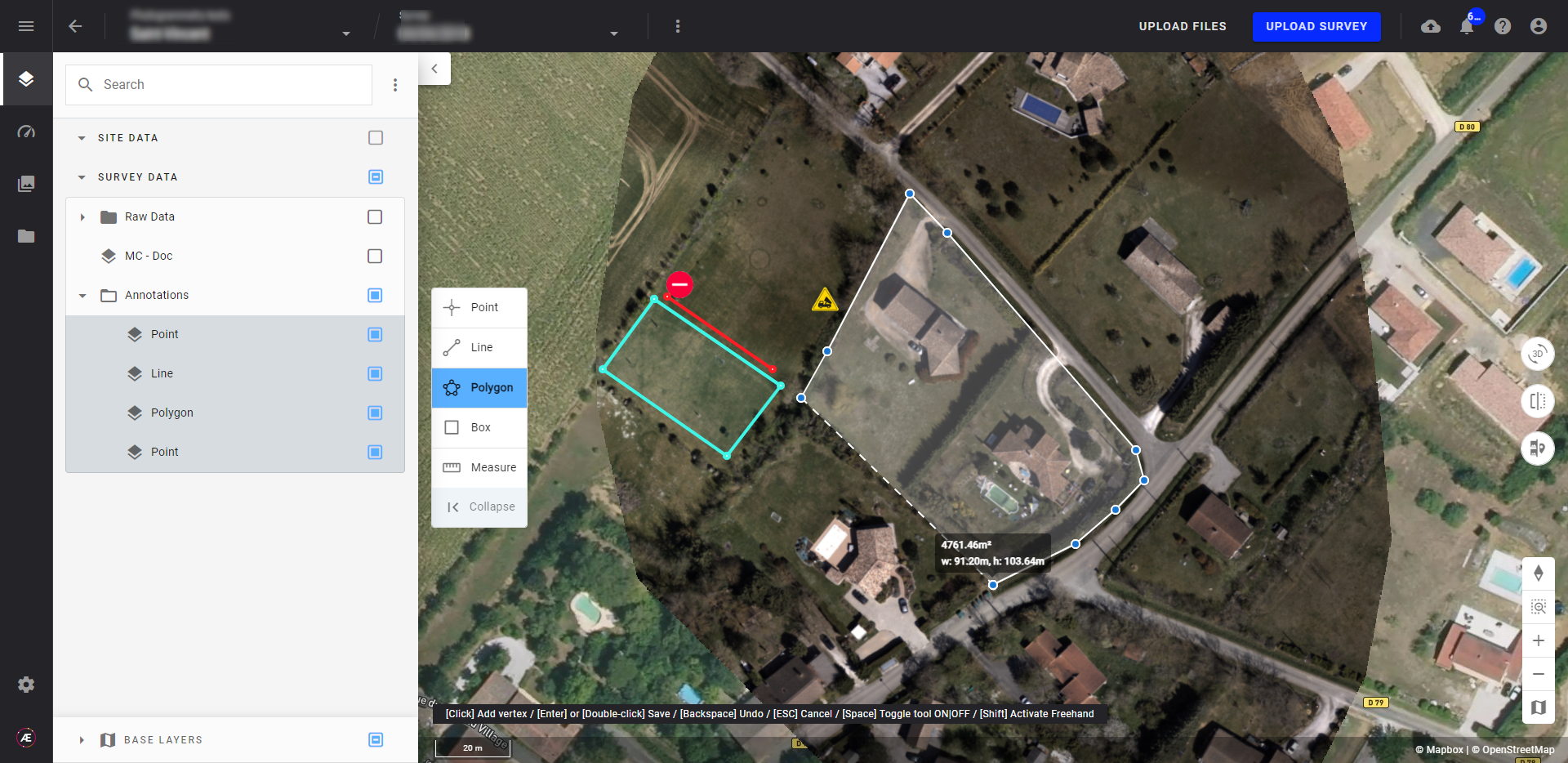
Step 1 - Within a survey, in the image, 2D or 3D view, from the toolbar on the left side of the screen, select the annotation tool corresponding to the shape you want to create among Point, Line, Polygon or Box (except for 3D)
Step 2 - Click on the map or the image to draw the annotation.
Step 3 - When drawing polygon, box, or line annotations, double-click the last point to save the annotation.
2.2 Rename an annotation
When creating an annotation, a generic name is assigned, which can be easily updated.
Using the Annotation panel:
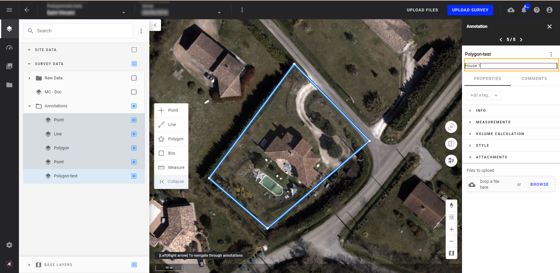
Step 1 - Click on the name of the annotation displayed at the top of the Annotation panel (right panel) and rename it.
Step 2 - Press ENTER to confirm the new name.
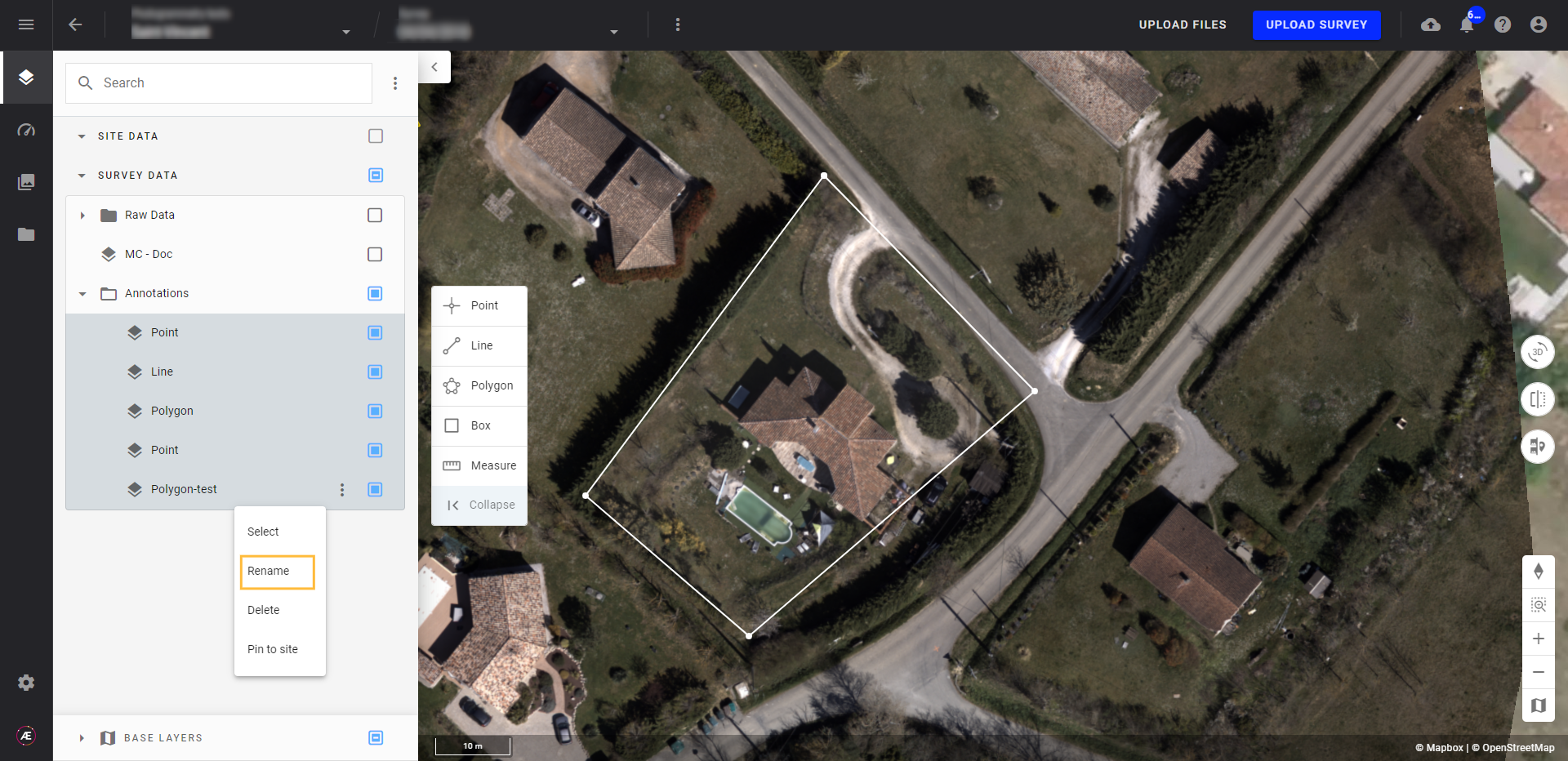
Using the 3-dot menu from the Annotation panel:
Step 1 - Select the 3-dot menu to the right of the annotation name.
Step 2 - Click "Rename".
Step 3 - Type the annotation name and press "ENTER" to confirm
2.3 Organize annotations
After creation, all annotations are found under the 'PROJECT DATA' and 'SURVEY DATA' groups in the Layers panel. Maintain organization by utilizing groups and subgroups of features, similar to managing layers, see Browsing and Arranging Layers.
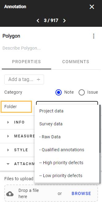
The user can also change an annotation from one group to another from the annotation panel, under the "PROPERTY" tab.
2.4 Describe an annotation
Characterize the annotation by adding a description, either directly from the annotation description or from the 3-dot menu in the Annotation panel
From the annotation description:
Step 1 - Click on the annotation and type the text in the "Describe" section.
Step 2 - Press "ENTER" to confirm the description.
Using the 3-dot menu (annotation panel):
Step 1 - Click on the 3-dot menu.
Step 2 - Select "Edit description".
Step 3 - Enter the description and press "ENTER" to confirm.
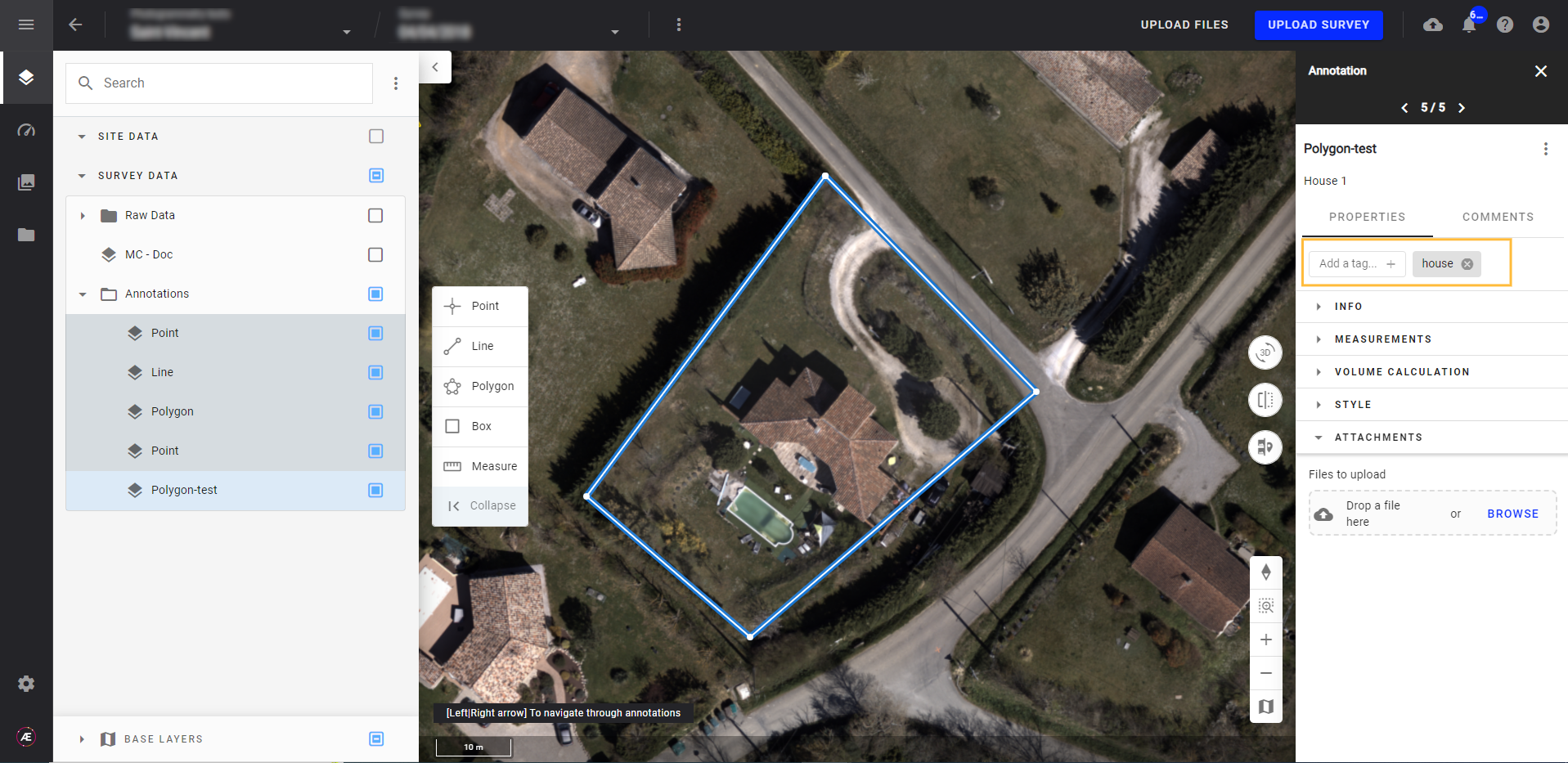
2.5. Characterize an annotation
To further characterize an annotation, use the annotation panel. In "PROPERTIES", select the annotation type between "Note" and "Issue".
- Note shall be used for simple observations
- Issue shall be used for defects.
If "issue" is selected, it displays a new block "issue details", listing all issue attributes.
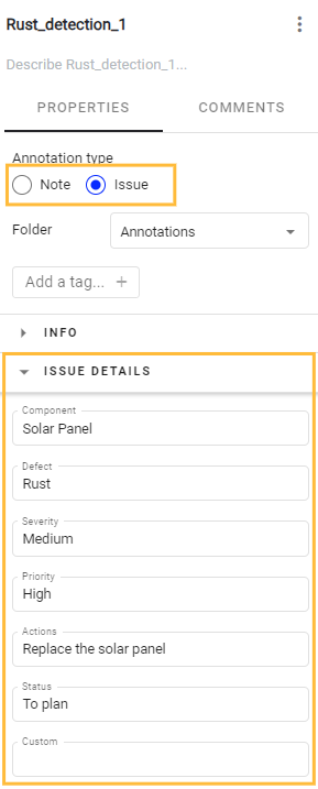
For the moment, the list of attributes is not configurable, and all values are "free text".
2.6. Add a tag to an annotation
Utilize annotations to swiftly navigate to projects by employing tags. Tags function as searchable elements, allowing access to a project by searching for a tag linked to an annotation within that project, directly from the project list.
Add one or more tags to an annotation from the Annotation panel:
Step 1 - Click on "+ tag" in the Annotation panel.
Step 2 - Enter a name for the tag and press "ENTER" to confirm.
2.7 Edit an annotation
Annotation properties can be updated through the annotation panel, as explained above. This paragraph addresses the update of the visual appearance of an annotation : shape, size and style.
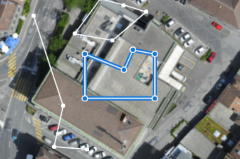
2.7.1. Edit the shape of the annotation
2.7.1.1. 2D and images annotations
Right-click on an existing annotation : it opens the following menu:
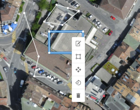
- Edit : enables the user to edit the lines, by moving, adding, deleting some points on the segment of the shape. Click on a line to add a point, Alt+Click on a point to delete it, click and grad to move a point, and press Enter to save the shape.
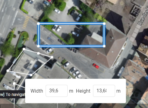
- Transform : this function is particularly useful for rectangles. It enables the user to change the width and height of the shape.
- Move : Just click on the shape and drag it. Once completed, press Enter to save.
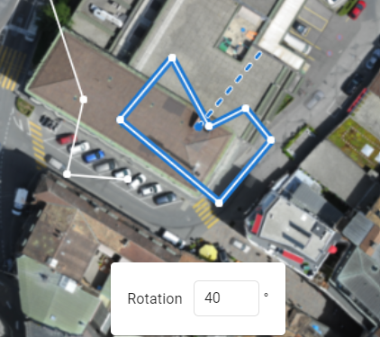
- Rotate : Enter the angle of rotation to apply to the shape, and press Enter to save.
- Delete : click on the bin to delete the annotation. A confirmation message appears, click on "CONFIRM" to validate the suppression.
Note : for points, there is only two options : "move" and "delete".
2.7.1.2. 3D annotations
Right-click on an existing annotation : it opens the following menu: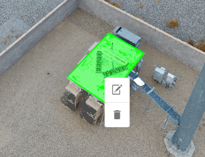
There are two options :
- Edit : enables the user to move the existing points of the shape. Click on "Enter" to validate, and on "Esc" to cancel the changes.
- Delete : click on the bin to delete the annotation. A confirmation message appears, click on "CONFIRM" to validate the suppression.
2.7.2. Edit the style of the annotation.
Give a style to the annotation by updating its parameters (opacity, color, etc.) under the "STYLE" section of the Annotation panel, which opens by clicking on an annotation.

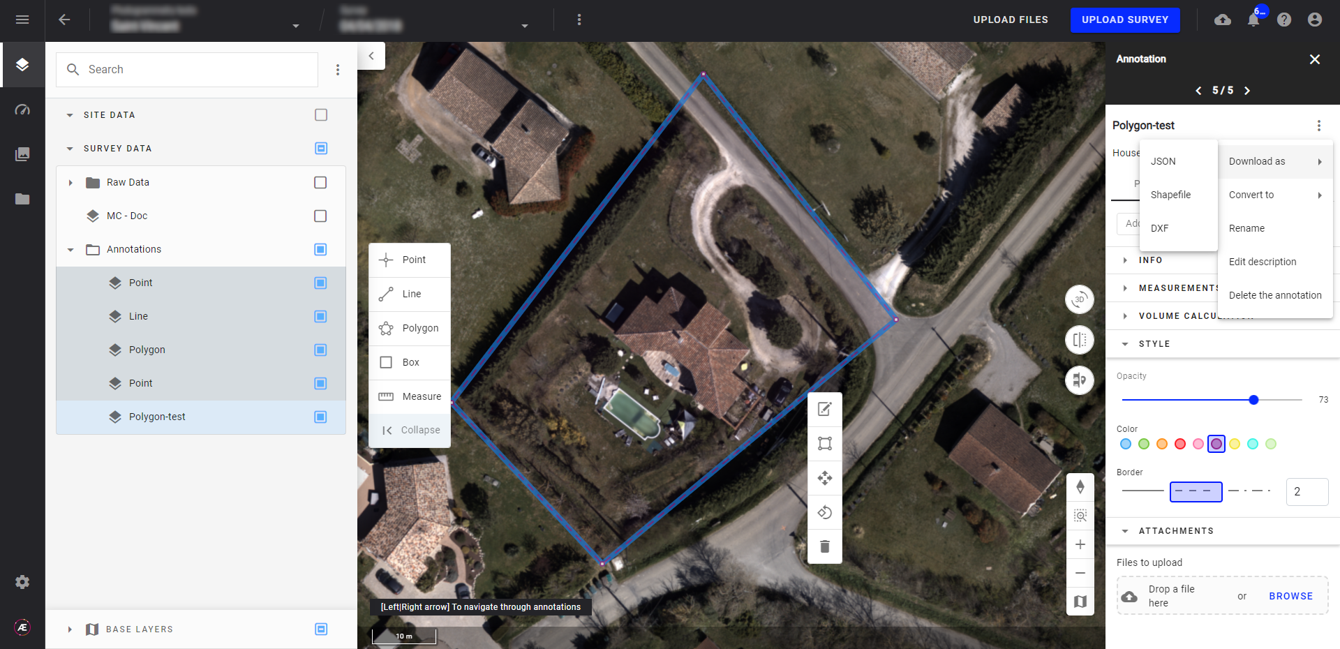
2.8 Export an annotation
Step 1 - Select which annotation to export.
Step 2 - Open the 3-dot menu close to the annotation name and select "Download as".
Step 3 - Select the prefered file format for export.
2.9 Delete an annotation
There are two ways to delete an annotation:
- From the Layers panel: Use the drop-down menu in front of the annotation (see Browsing and Arranging Layers)
- From the 3-dot menu of the Annotation panel: Open the 3-dot menu, and click on "Delete the annotation" and confirm.
2.10 Convert a 3D annotation to a 2D annotation.
Step 1 - Open the 3D view and select an existing 3D annotation, or create a new one.
Step 2 - Open the 3-dot menu of the annotation and click on "Convert to 2D".
Step 3 - A new annotation is created and displayed in the 2D view.
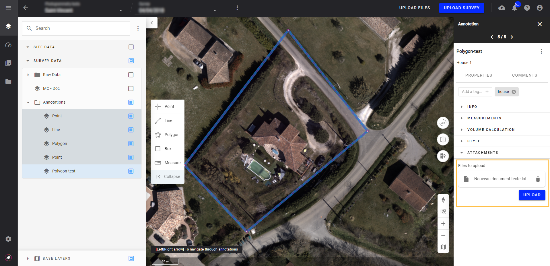
2.11 Attach a file to an annotation
Attach a file (image, PDF report, graph, video, etc.) to an annotation.
Step 1 - Select "ATTACHMENTS" from the Annotations panel.
Step 2 - Browse for a file using the "Browse" button or directly drag and drop the file.
Step 3 - Once uploaded, a preview of the file will appear in the panel.
3. Business uses cases
Harnessing annotation tools proves indispensable in deriving valuable insights from spatial data, offering a wide range of applications for businesses.
3.1 Calculate perimeter, surface, and volume
Use the Polygon Annotation Tool to create annotations that outline the perimeter of objects such as microplots or stockpiles. As the annotation is created, the tool automatically calculates metrics such as area, perimeter, and volume, which are conveniently available in the annotation panel.
The Box annotation (2D only) serves a similar purpose, delineating the perimeter of objects within a rectangular shape.
3.2 Generate a boundary vector layer
For analytics requiring vector file inputs of area boundaries, convert a polygon annotation into a vector layer using the annotation tool:
Step 1 - Click on the three dots menu of the annotation.
Step 2 - Select "Convert to."
Step 3 - Opt for "Field boundaries."
3.3 Get location coordinates
A point annotation helps read the specific coordinates and elevation at a specific location.
Select the Point Annotation tool from the toolbar and click on the desired location for measurement on the map.
Once created, select the annotation and the location information will automatically appear in the annotation panel.
3.4 Mark specific situations
Use point coordinates to mark permanent, temporary, or specific situations such as hazardous areas. Aether's built-in icon library enhances this capability: select the point annotation, navigate to the annotation panel, and choose "Style" to assign a relevant icon.
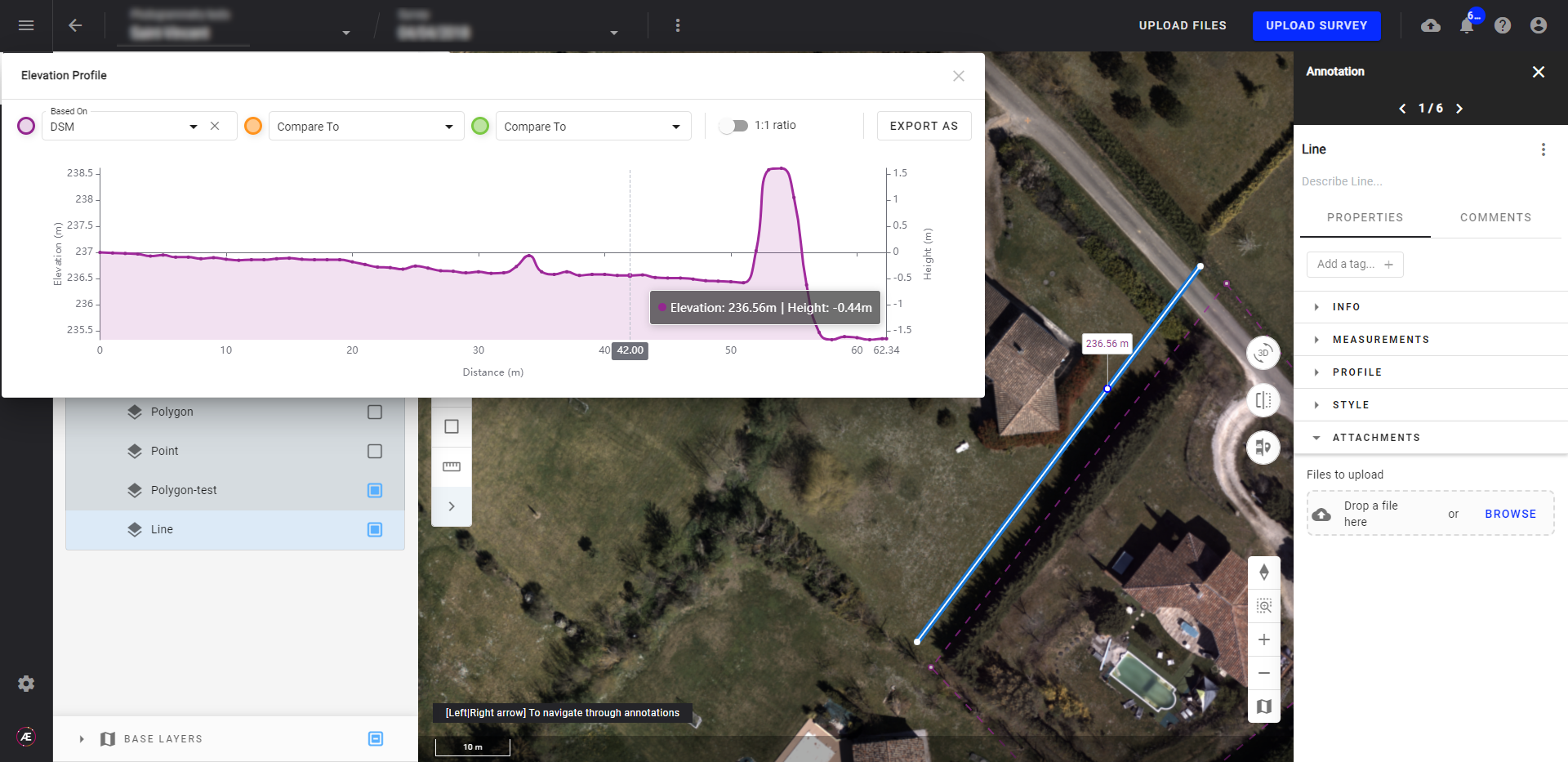
3.5 Measure Distance on a Layer and Calculate Elevation Profiles
The line annotation proves beneficial for measuring distances on a layer and calculating elevation profiles:
Step 1 - After creating the line annotation, select "Profile" from the Annotation panel.
Step 2 - Choose "Elevation profile."
The resulting "Elevation profile" window displays elevation as a function of position on the line, making comparisons easy.
Hover the mouse over the line to get elevation values at each point, or quickly identify the location of an elevation by hovering it on the graph: its position will be highlighted on the line.
"Height" describes the elevation difference between the cursor position and the first point of the profile.
"Diff" represents the elevation difference between a DSM (based on) and another DSM (Compared to).
This tool enables the comparison of up to three elevation profiles simultaneously.
Additionally, export the elevation profile to a vector file, including JSON, Shapefile, DXF, and FPC, through the "Export as" feature in the elevation profile window. The vectors generated are referenced to the WGS84, EPSG:4326 global coordinate system.
4. Additional measurements
Perform additional measurements for all vector annotations (point, line, polygon, and box), by expanding the Measurements section and clicking on the "Measures" button.
5. Measure tools
Instantly obtain measurements without creating and saving annotations.
Measure coordinates, distance, average slope, elevation profiles, area, and volume.
While data from the measure tool is not saved by default, users can preserve insights by clicking the "Save" icon.
For detailed information on measurement tools, refer to the article Measurement Tool.
6. Generate an annotation report
Generate a comprehensive PDF report encompassing all annotations within the project, see the Annotation Report section.
