

Drone Flight Parameters
1. Description
Discover the essential guidelines and settings for maximizing performance and adjusting flight parameters to achieve optimal results.
2. Flight Parameters for Power Line Inspection
This section outlines the data acquisition recommendations for processing RGB imagery in the Digital Inspection module.
2.1 Parameters
Hardware:
- Camera: High-resolution sensor yielding a Ground Sample Distance (GSD) sufficient to resolve the smallest targeted defect.
- Lens: Wide-angle to maximize field of view and structural context.
Picture metadata requirements:
- Camera brand, maker, type, lens type
- GPS date and time
- GPS coordinates (longitude, latitude and altitude)
- Camera orientation (roll, pitch, yaw angles)
- Lens focal length in the x and y directions
- Lens distortion
- Coordinates of the optical center of the camera
- Shutter speed
- Pixel size of the sensor
- Pixel pitch of the sensor
- Horizontal and vertical Field of View angles
2.2 Data acquisition recommendations for distribution asset inspection without 3D reconstruction
Flight protocol (6 images):
- Capture the first full‑pole image from the front of the pole (Overall view 1).
- Move to a low‑angle profile view to capture detailed images of the insulator strings (Zoomed view 1).
- Ascend to the level of the crossarm to capture a detailed image (Zoomed view 2).
- Move to a diagonal position to capture the crossarm from an oblique angle (Zoomed view 3) .
- Reposition to the opposite profile side to capture another detailed view (Zoomed view 4).
- Finally, capture a second full‑pole image from the opposite side of the pole (Overall view 2).

2.3 Data acquisition recommendations for 3D‑based distribution asset inspection
Flight protocol (10 to 20 images):
- Detail Ring (8 to 16 images): 360°orbit around the pylon head. Camera tilted down (ground as background, strictly no sky).
- Context Views (2 to 4 images): Wider shots framing the entire pole and environment for structural anomaly detection.
- SfM Distance Ratio: To ensure seamless 3D alignment in the Structure from Motion algorithm, the flight distance for Context Views must be 2 to 3 times the distance of the Detail Ring.

Positioning & Data
- RTK & Metadata: The use of an active RTK module is recommended. Embedding centimeter-level spatial coordinates (X, Y, Z) directly into the image EXIF/XMP data improves the performance, speed, and reliability of the SfM reconstruction when working with a low image count.
2.4 Data acquisition recommendations for transmission asset inspection
For transmission asset inspection, flight requirements vary depending on the asset type and the number of conductors. Please contact us for more details.
3. Flight Parameters for Solar Panel Inspection
3.1 Parameters
| Products | ||
| MULTI-ROTOR | LiDAR mVux |
|
| Multi-spectral |
3.2 Recommendations
- A minimum of 80% overlap is required
- IR camera must be radiometric with a minimum resolution of 640 x 480
- The recommended format is Radiometric JPEG
- Suggested Drone: DJI Matrice 200 series
- Suggested sensor: Zenmuse XT2
4. LiDAR Data Acquisition requirements for Vegetation detection
4.1 Format
- Point cloud density: minimum 50 pts/m², ideally around 70 pts/m² to facilitate analysis.
- Deliverable formats : LAS or LAZ 1.4 version 2 (RGB available).
- The point cloud can be colorized (photos must therefore be taken simultaneously with the LiDAR survey).
- GNSS–LiDAR system synchronization is ensured by the service provider.
-
Data positioning accuracy is ensured by the service provider: an accuracy of approximately 15 to 20 cm is expected (RTK drone required).
- Ground Control Points:
- The Ground Control Points have to be tagged in the LiDAR software.
- When tagging the GCPs in the LiDAR Software, each drone axis has to be tagged separately.
- Please contact your LiDAR sensor manufacturer for more information on GCP best practices (type and size of GCPs to be used…)
- Ground Control Points:
-
The projection system must be specified in the file:
- UTM projection (WGS84) with local ellipsoidal height.
- Either UTM30N (EPSG:32630), UTM31N (EPSG:32632), or UTM32N (EPSG:32630) for mainland France.
4.2 Data quality
- The LiDAR coverage width must be 40 m (20 m on each side of the line axis), measured at ground level.
- Conductors and poles must be visible in the point cloud.
- No line duplication should be observed.
- Point clouds must not contain excessive noise.
- Merging multiple .LAS files is handled by the provider without any alignment issues.
5. Flight Parameters for Corridors
5.1 Parameters
| Product | ||
| FIXED WING | RGB |
|
| LiDAR mVux |
|
|
| MULTI-ROTOR | RGB |
|
5.2 Recommendations
(2) Depending on both the Vegetation Corridor width and expected point cloud density requirement. For ex: the side overlap for transmission lines is 30m
- For projects involving multiple flights, sufficient overlap should be maintained between flights.
6. Flight Parameters for Mining and Aggregates
6.1 Parameters
| Products | ||
| FIXED WING | RGB |
|
| MULTI-ROTOR | RGB |
|
6.2 Recommendations
- For projects with multiple flights, there should be an overlap between the different flights and the conditions (sun direction, weather, etc.)
-
Recommended camera settings:
- Exposure time: less than 1/1000 sec
- ISO sensitivity: less than 400
- Fixed focal length; Infinite focus
7. Flight Parameters for Trial Fields and Production Fields (Agriculture)
7.1 Parameters
| Products: |
Scouting maps Plant Height Fcover / Flowering / Staygreen |
Plant count / Emergence | |
|
MULTI-ROTOR & FIXED WING |
RGB and Multi-spectral |
GSD: 1 to 10cm Forward overlap: 80% Side overlap: 80% Flight speed multi-rotor: max 8m/s |
GSD: 1 to 5cm (1) Forward overlap: 80% Side overlap: 80% Flight speed multi-rotor: max 8m/s |
7.2 Recommendations
-
If there are multiple flights in the same Area of Interest (for a campaign), they need to be co-registered:
- Set measured Ground Control Points (GCPs): at least one at each corner of the field + one in the middle of the field
- Or the UAV must be equipped with PPK or RTK function: we recommend using a mobile GNSS station. If you use a fixed known GNSS station, the maximum distance to the Area of Interest is 15km.
- Avoid flying during the azimuth sun period or when the sun is low (shadows)
- Avoid flying when the weather is alternating between sunny and cloudy
- No water or snow over the canopy
- Take pictures of the calibration panel BEFORE and AFTER the flight (multi-spectral). Follow sensor manufacturer guidelines + See Paragraph 9.
- Add additional UAV trajectories outside the Area of Interest to ensure collecting enough good-quality pixels within the field boundaries
- Avoid flying over disturbing elements that could affect the reflectance such as buildings or cars.
-
Specific recommendations for rolling shutter sensors:
-
Stop the drone when taking a picture if drone capacities allow it or:
- Ensure flight speed is max 5m/s and the speed is stable during the entire flight
- Set shutter time to max 1/600 and stable during the entire flight
- Overlap: 85%
-
Stop the drone when taking a picture if drone capacities allow it or:
(1) The Plant Canopy Size must be equal to twice the GSD. Ex: Canopy size is 8 cm, GSD must be 4 cm
8. Flight Parameters for Plantation and Forestry
8.1 Parameters
| Products: | Scouting maps | Fcover |
DTM Estimation Plant height Tree count |
|
| MULTI-ROTOR & FIXED WING |
RGB Multi-spectral |
GSD: 5 to 15cm (1) Forward overlap: 80% Side overlap: 80% Flight speed multi-rotor: max 8m/s |
||
8.2 Recommendations
-
If there are multiple flights in the same Area of Interest (for a campaign), they need to be co-registered:
- Set measured Ground Control Points (GCPs): at least one at each corner of the field + one in the middle of the field
- Or the UAV must be equipped with PPK or RTK function: we recommend using a mobile GNSS station. If you use a fixed known GNSS station, the maximum distance to the Area of Interest is 15km.
- Avoid flying during the azimuth sun period or when the sun is low (shadows)
- Avoid flying when the weather is alternating between sunny and cloudy
- No water or snow over the canopy
- Take pictures of the calibration panel BEFORE and AFTER the flight (multi-spectral). Follow sensor manufacturer guidelines + See Paragraph 9.
- Add additional UAV trajectories outside the Area of Interest to ensure collecting enough good-quality pixels within the field boundaries
- Avoid flying over disturbing elements that could affect the reflectance such as buildings or cars.
-
Specific recommendations for rolling shutter sensors:
-
Stop the drone when taking a picture if drone capacities allow it or:
- ensure flight speed is max 5m/s and the speed is stable during the entire flight
- Set shutter time to max 1/600 and stable during the entire flight
- Overlap: 85%
-
Stop the drone when taking a picture if drone capacities allow it or:
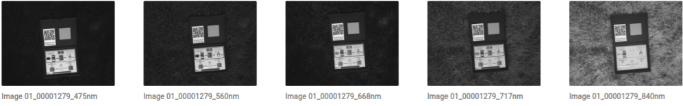
9. Calibration Target Best Practices
Follow recommendations from the sensor manufacturer.
Complementary recommendations:
-
Take pictures of the calibration target BEFORE and AFTER the flight
- Calibration targets must be placed on the ground
- Pictures have to be taken by the operator with the drone
- Take pictures as close as possible to the calibration target to minimize reflectance from the objects outside the calibration target
- Calibration targets must be placed on the ground
-
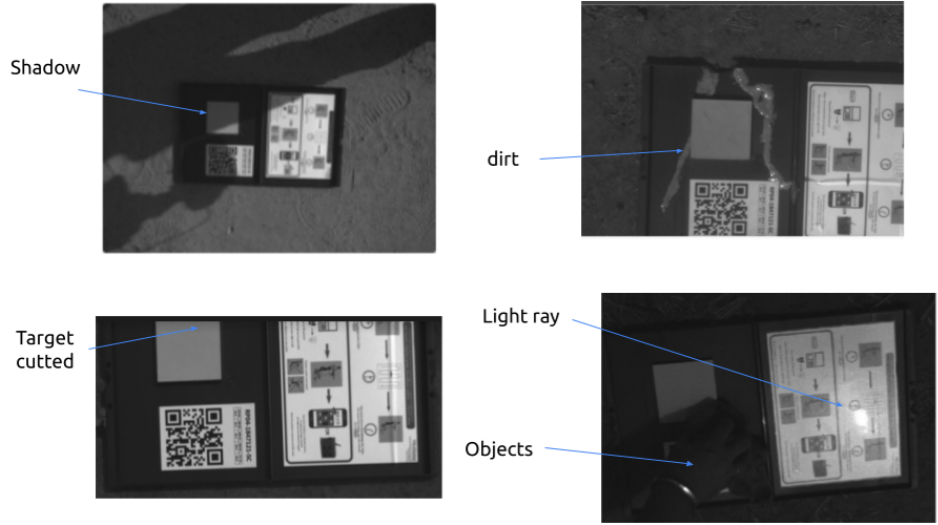
Avoid disturbing elements on the whole picture (including inside and outside the calibration target): shadow, light rays, reflective objects...
- If possible, add a black/mat “tarpaulin” behind the calibration target to avoid disturbing objects on the whole picture. The type of material should be selected attentively to avoid light rays. This is in particular recommended when an irradiance sensor is mounted on the drone.
-
Only one set of images (including one image per spectral band) has to be selected and uploaded in Aether.
-
To select the right set of images:
- 1) Open the post-flight folder and locate the “Calibration” images folder. Under the Calibration folder, you must start with the Blue Band.
- 2) Find the image with no shadows over the panel and with the least “exposure time" (check image settings) keep that one, and delete the rest of the images of that blue band.
-
To select the right set of images:

- For the Green, Red, Red-Edge and Near Infrared bands, keep the image with the same reference “Image name” as the Blue Band and delete the rest. You should end up with 1 image of each band (Green, Red, Red-Edge, Near Infrared, etc...) with the same reference in the calibration folder.
