

Photogrammetry
1. Description
Photogrammetry is a technique that enables the generation of 2D and 3D models from a dataset of geotagged images. This process involves analyzing images of a subject taken from various angles and distances to create a digital model of it.
2. Workflow
Step 1 - Open a project.
Step 2 - From the "Analytics" tab, in the "COMPUTING TOOL" section, click on "Photogrammetry".
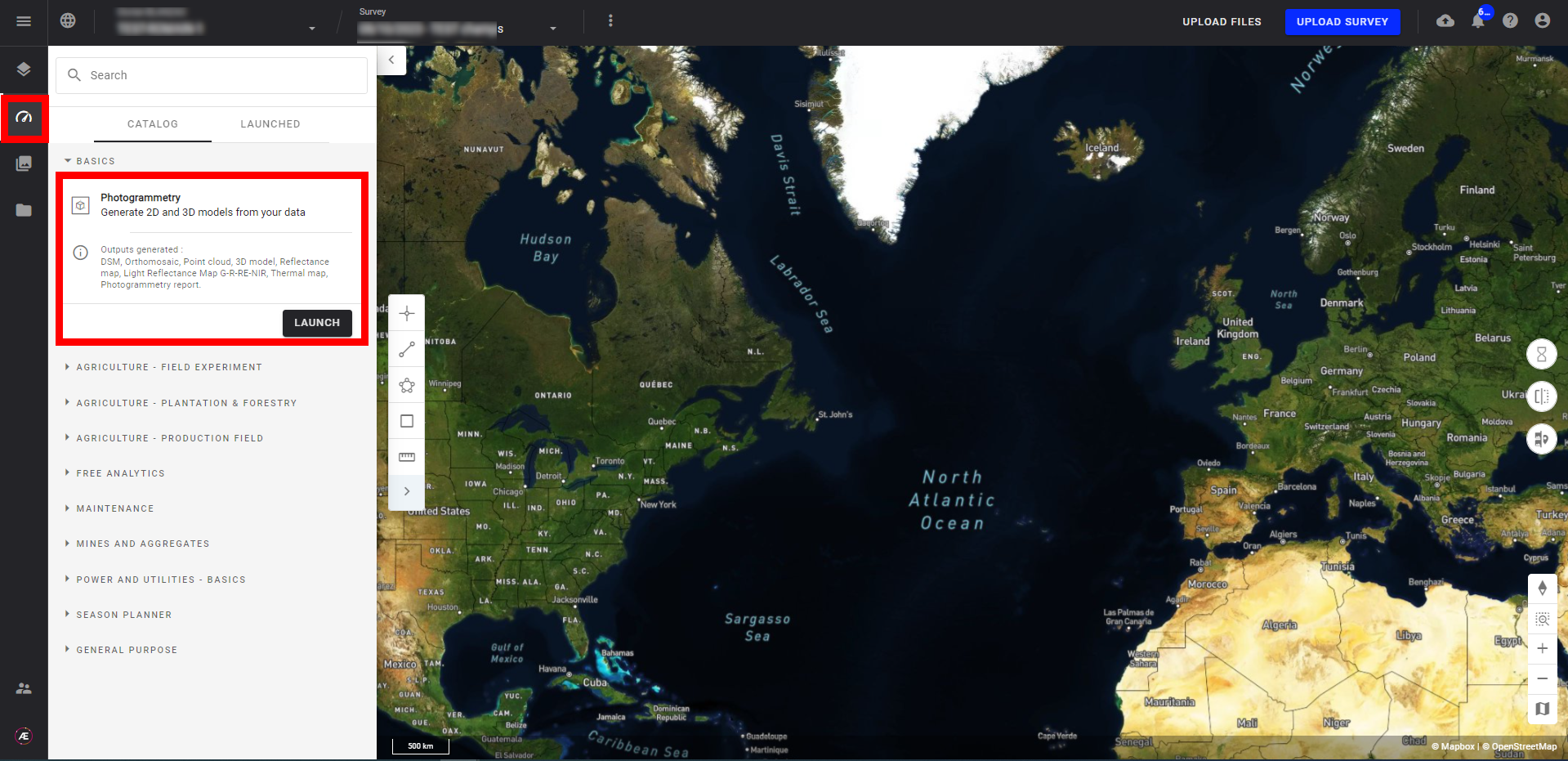
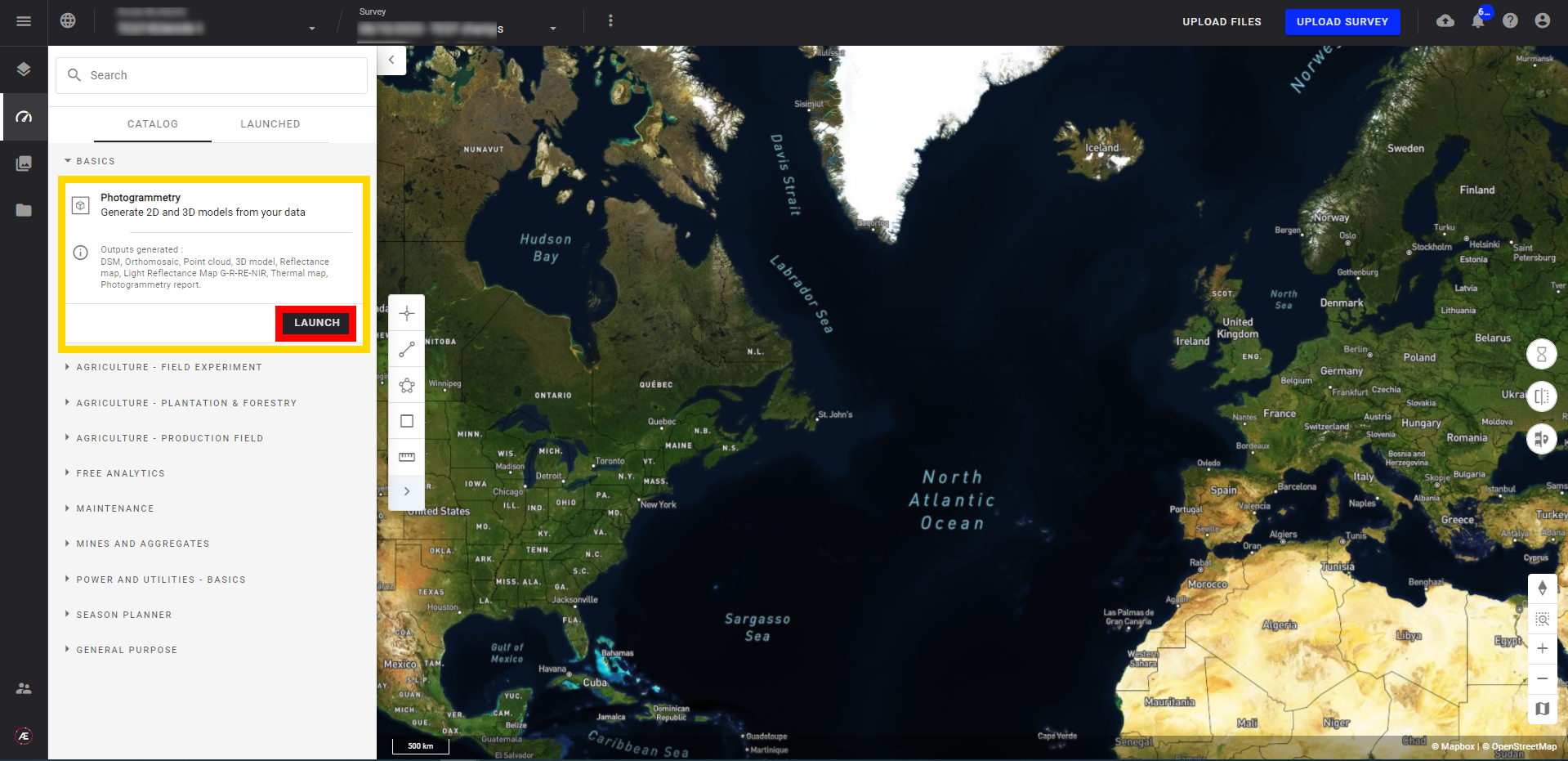
Step 3 - Click on "LAUNCH".
Step 4 - Consult and update the parameters if necessary. Parameters are detailed in the Paragraph 3.
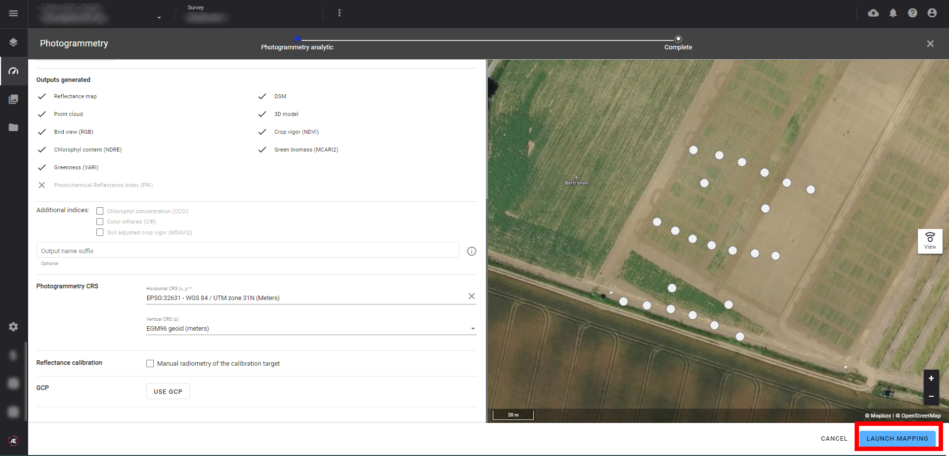
Step 5 - Click on "LAUNCH MAPPING".
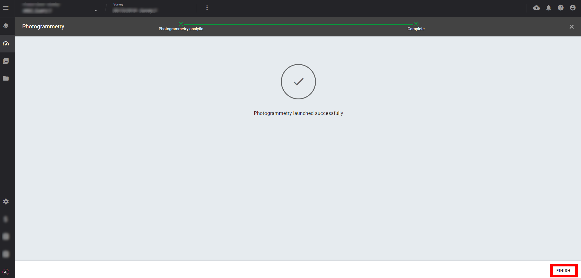
Step 6 - The Photogrammetry is launched. Click on "FINISH"
Optional Steps
Between Step 4 and Step 5, there could be some optional steps.
Optional Step - Clean
When a photogrammetry has already been launched on the same survey, a "Clean" step appears. At this step, the user can choose to clean previous photogrammetry results or to keep them. By default, the previous results are kept. If you want to clean previous results, check the box.
The previous photogrammetry results are deleted as soon as the user clicks on the “LAUNCH MAPPING” button.

Please note that if any analytics were launched based on the previous photogrammetry outputs, the results of those analytics will not be deleted.
Optional Step - Data Capture
When a photogrammetry is launched for a survey linked to a data capture task, a "Data Capture" step appears. At this step, the user can choose to use the results of the photogrammetry as outputs of the data capture task or not. By default, the results are used for the capture task. If you don't want to use results as outputs of the capture task, uncheck the box.

Note that if there are already outputs linked to the capture task, they will be replaced by the new photogrammetry outputs. In that case, the 2 optional steps will be visible : "Clean" and "Data Capture". The user can choose to replace the results of Data Capture without deleting previous photogrammetry outputs.
3. Information and Parameters
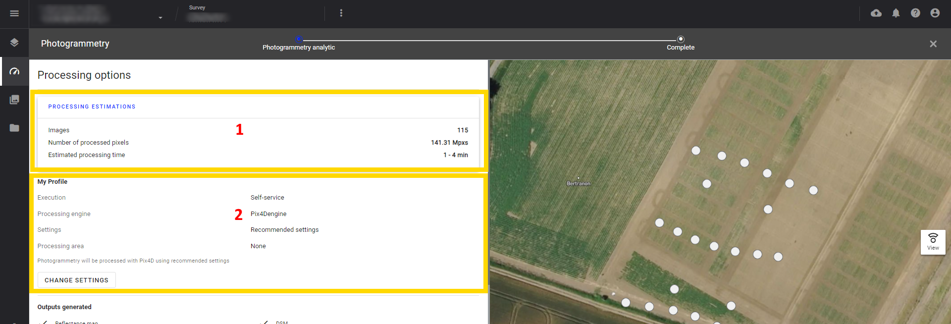
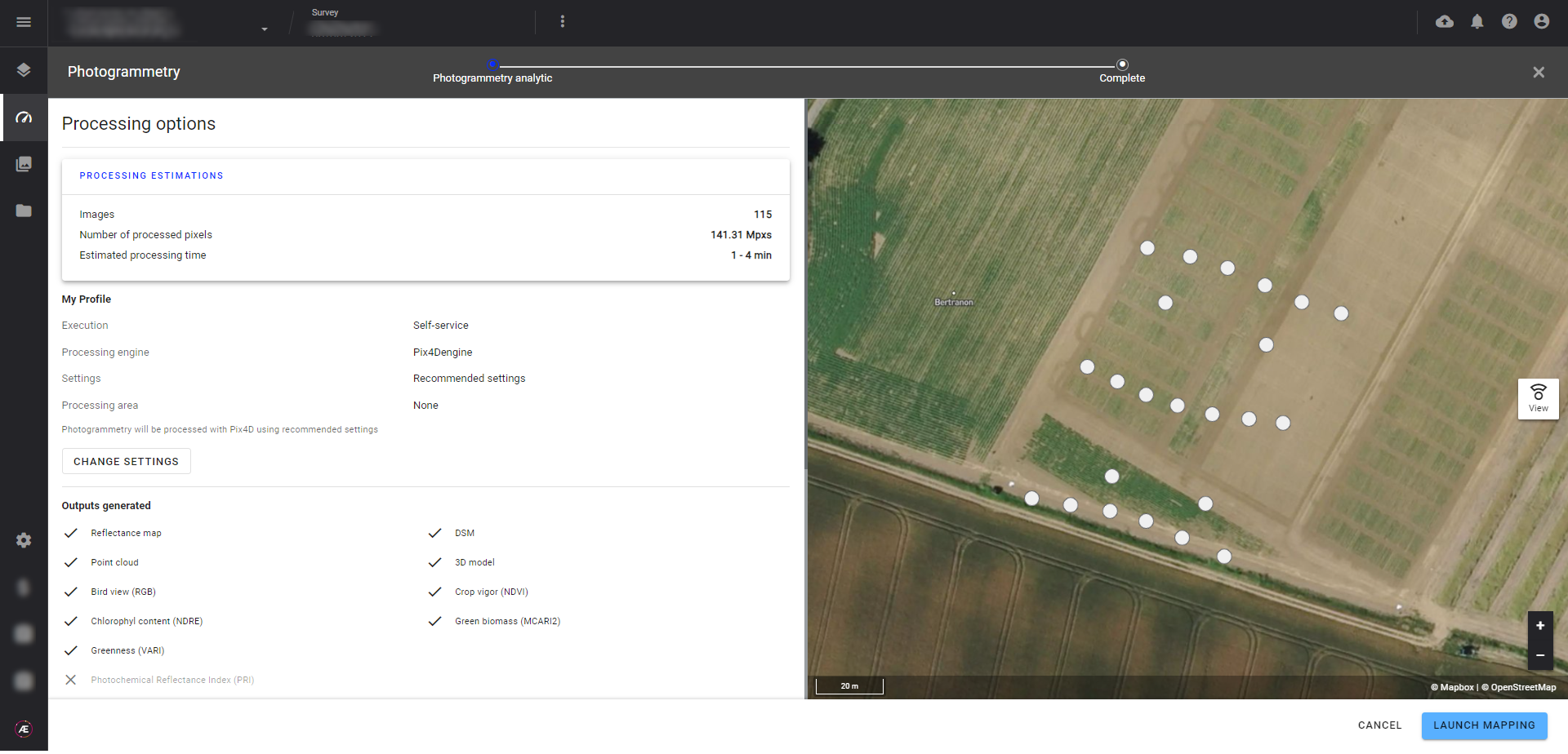
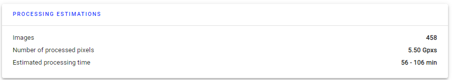
3.1 Processing estimations
Information about the number of images, processed pixels, and processing time.
3.2 My profile
In this section, you can define the execution mode, the processing engine, the settings and the processing area.

Execution mode:
Whatever the processing engine, you can choose between 2 execution modes: self-service or advanced.
- Self Service: photogrammetry is launched and results are published automatically, without the assistance or quality check of an Alteia production member.
- Advanced: photogrammetry is handled by an Alteia production member, who controls the results manually before publishing them on Aether.
Processing engine and settings:
By default, photogrammetry is set to the most common and widely used settings. However, it is important to note that these settings may not always be the most appropriate for your specific needs. Therefore, it is recommended that you take the time to review and adjust the settings to ensure the best possible results for your project.
For a more detailed understanding of the photogrammetry engines and options, we recommend that you refer to the article Photogrammetry Engines and Options.
Note that it's possible to define photogrammetry presets at Project and Company level.
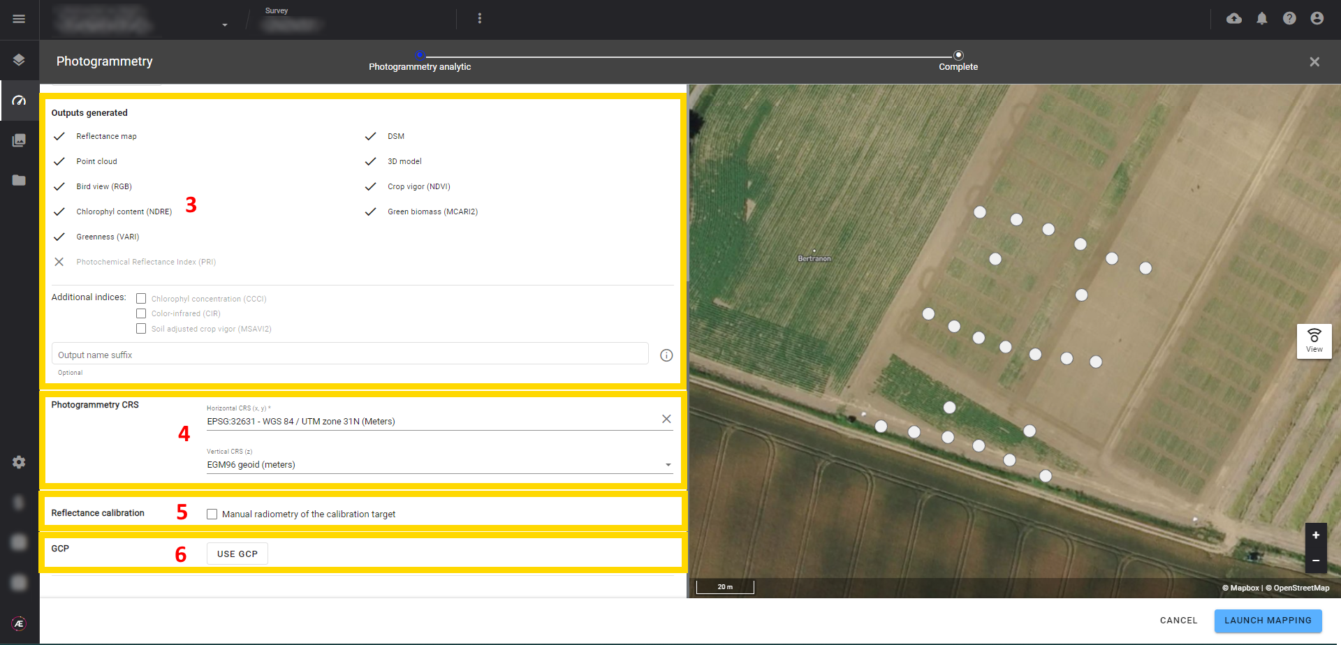
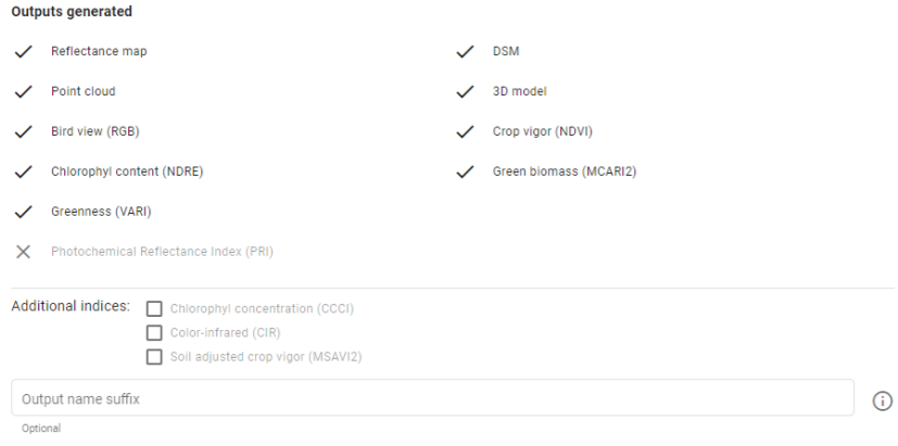
3.3 Outputs generated
The output generated from the photogrammetry process will be defined by default based on the type of sensor used to capture the photos (RGB, multispectral, thermal sensors).
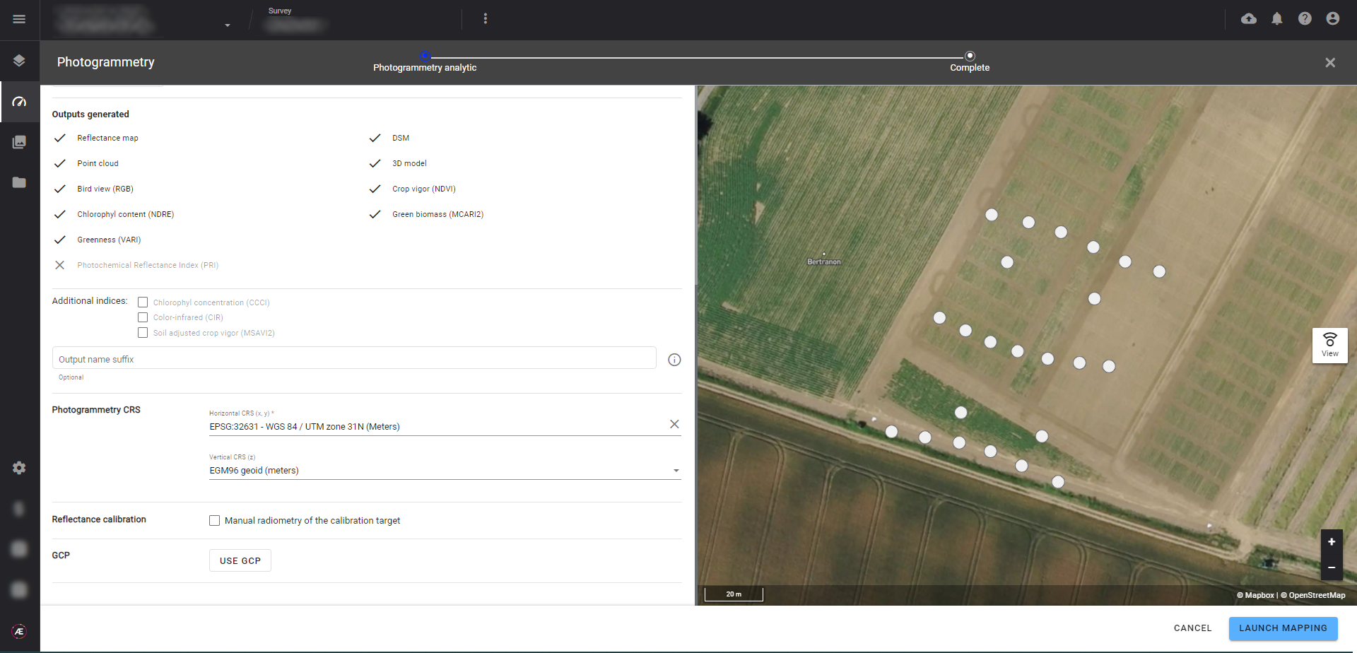
In the case of a multispectral camera, additional indices can be selected.
If needed, suffixes can be added to the output names.
In addition, a photogrammetry accuracy report is generated. Please refer to Photogrammetry Accuracy Report to get more details on how to access to this report and a description of its content.
3.4 Photogrammetry CRS
The Platform suggests a CRS for photogrammetry outputs, but it can be changed to fit the project needs (refer to Coordinate Reference Systems (CRS)).
3.5 Reflectance Calibration (multispectral)
If calibration needs to be processed manually, click on "Manual radiometry of the calibration target".
Cases where manual reflectance calibration is necessary:
- Automated calibration failed during the first attempt (refer to Calibration Verification for Reflectance Map).
- The calibration target is an old model (ref <RP04 for Micasence).
- Following a recommendation from Alteia Support.
3.6 GCP
If you have placed and measured ground control points (GCPs) before the flight, click on the “USE GCP” and drag and drop your GCP file.
For more detailed information about uploading, tagging or re-using existing GCP files, please read the dedicated article here.
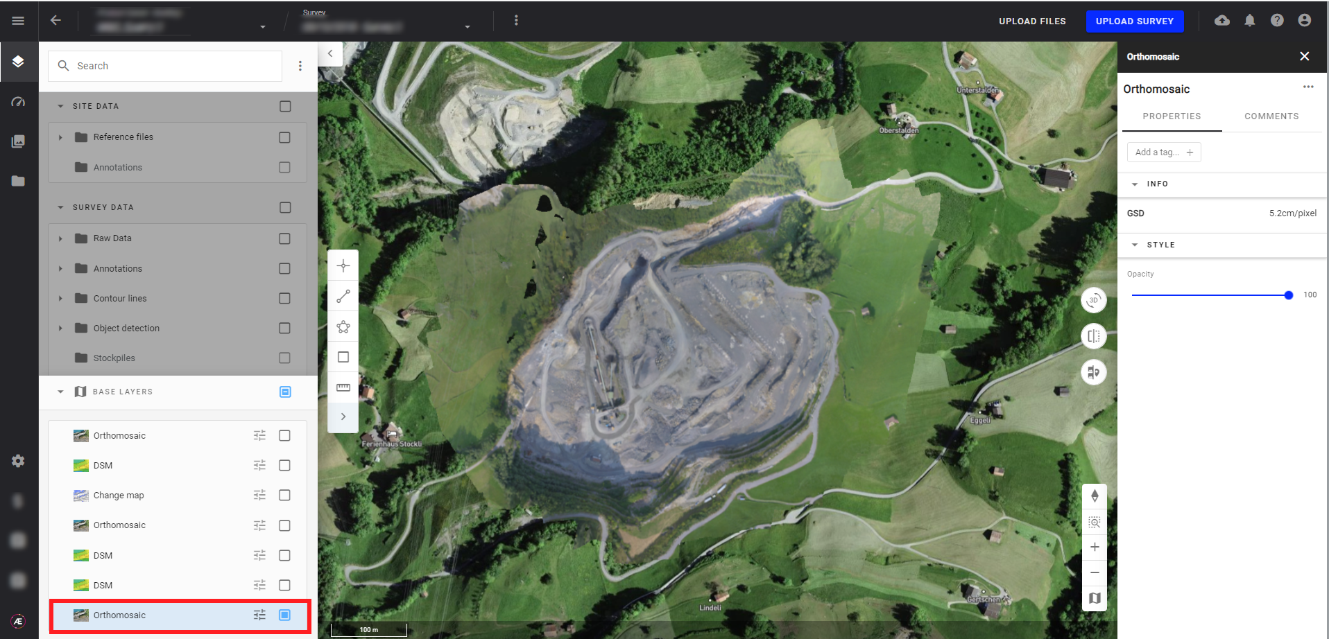
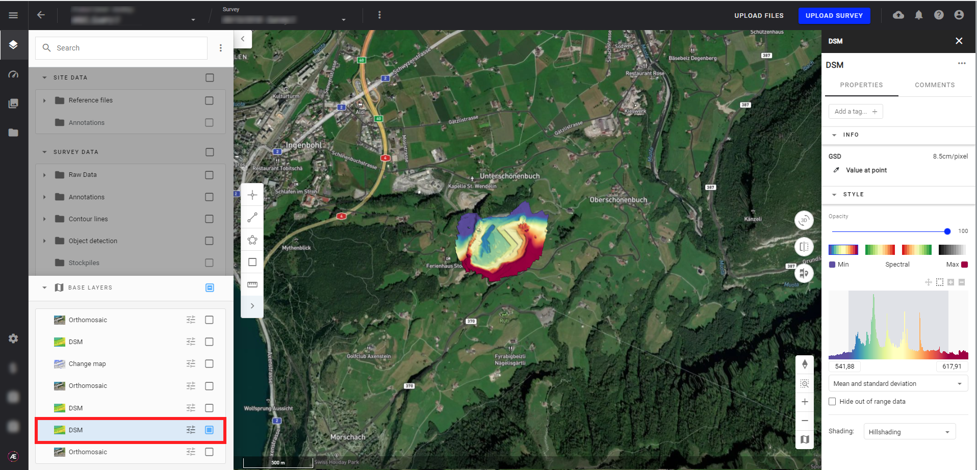
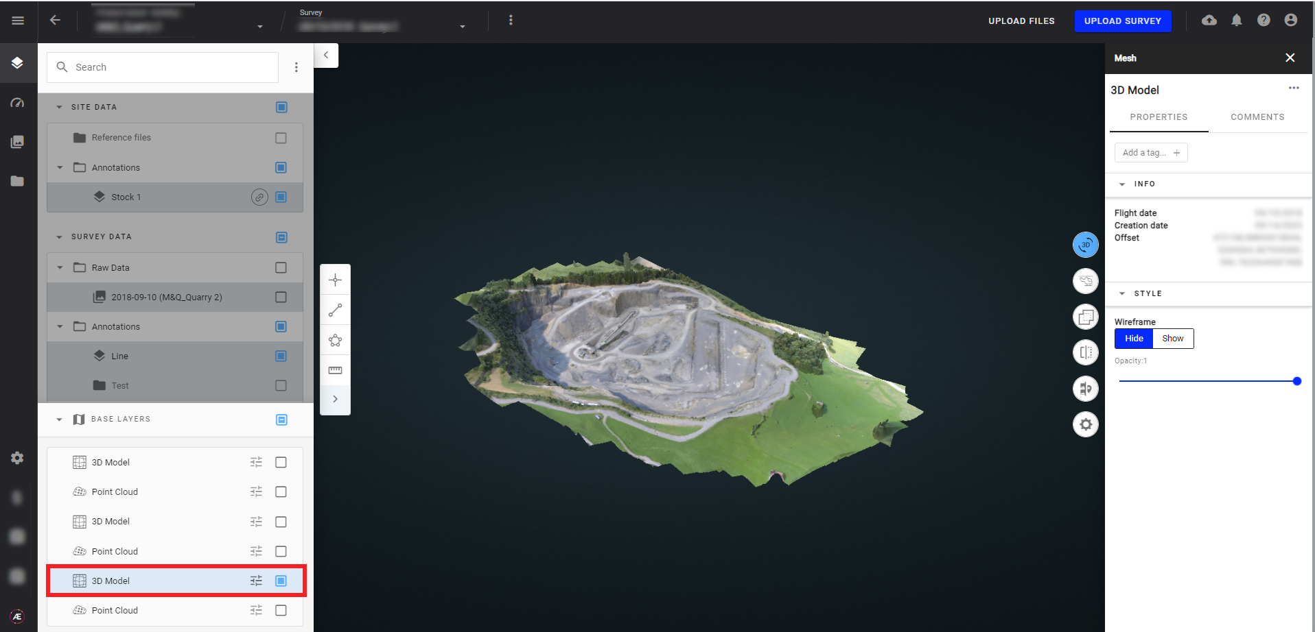
4. Results
After processing, the photogrammetry outputs are available in Data Studio 2D and 3D modes. Here are some examples:
- Orthomosaic
- DSM
- Point cloud
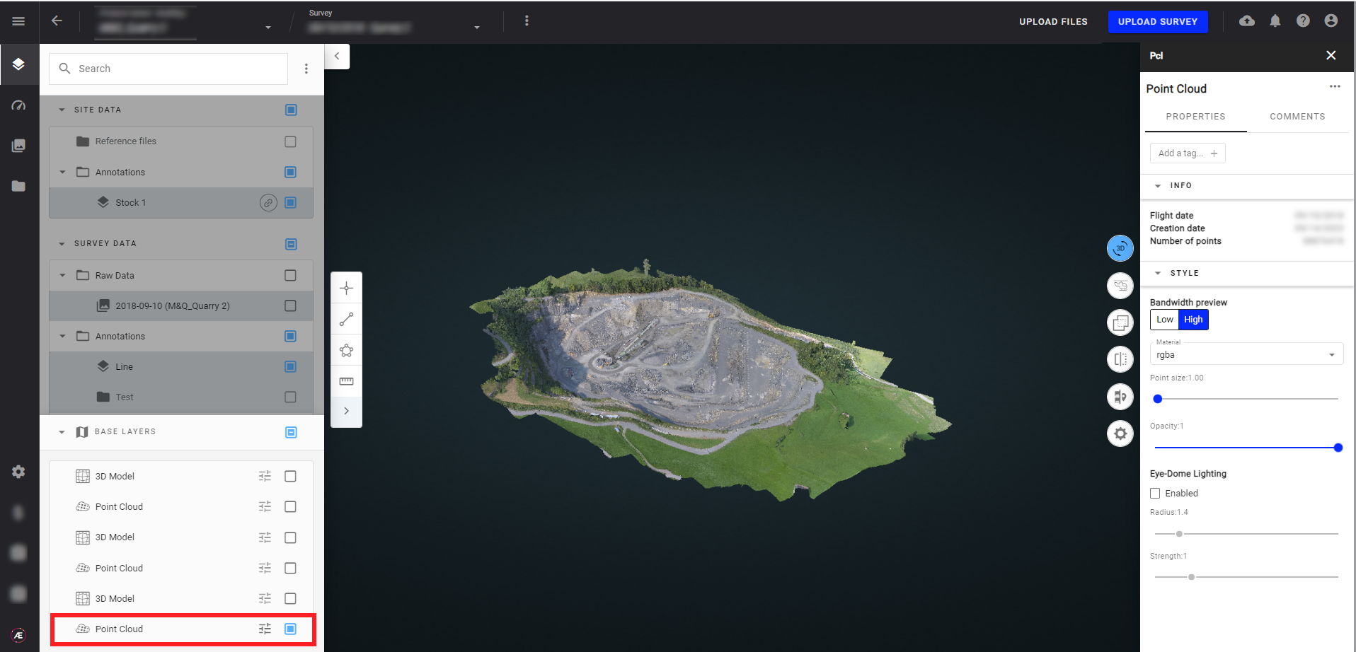
- 3D Model
5. Setting photogrammetry presets
According to your business, you may require only one engine on a daily basis. It is possible to define your preferred Photogrammetry Engine as a preset for the Company (with all its projects) or within a certain Project.
5.1. For an existing Project
Step 1 - Open a Project and select Show project info from the top bar drop-down menu

Step 2 - In the right panel, go to the "PHOTOGRAMMETRY PRESETS" section and click on "CREATE":

Step 3 - A pop-up will open with the photogrammetry settings. Adjust the settings (description given in section 6 below) and then click SAVE.

The information panel displays a message indicating that presets are being applied and lists the selected options.

This preset could be updated anytime later.
5.2. For an entire Company
Company Managers have administration rights allowing them to define the settings that will apply across all managed Projects, per Company.
Step 1 - At the bottom of the left panel, press Administration icon.

Step 2 - Click on "Companies" (1) and select the company on the list (2), for which you want to adjust the photogrammetry default settings.

Step 3 - Click on "CUSTOMIZE PRESET" in the Photogrammetry settings section.

Step 4 - A pop-up will open with the photogrammetry settings. Adjust the settings (description given in section 6 below) and then click SAVE.

6. Metrics
The following metrics are calculated for any photogrammetry task:
- Number of pixels : Gives the total number of pixels of all processed images
- Surface (not available for Pix4D V1): Gives the surface in meters of the DSM or orthomosaic or reflectance map if DSM not available.
