Digital Terrain Model (DTM)
1. Description
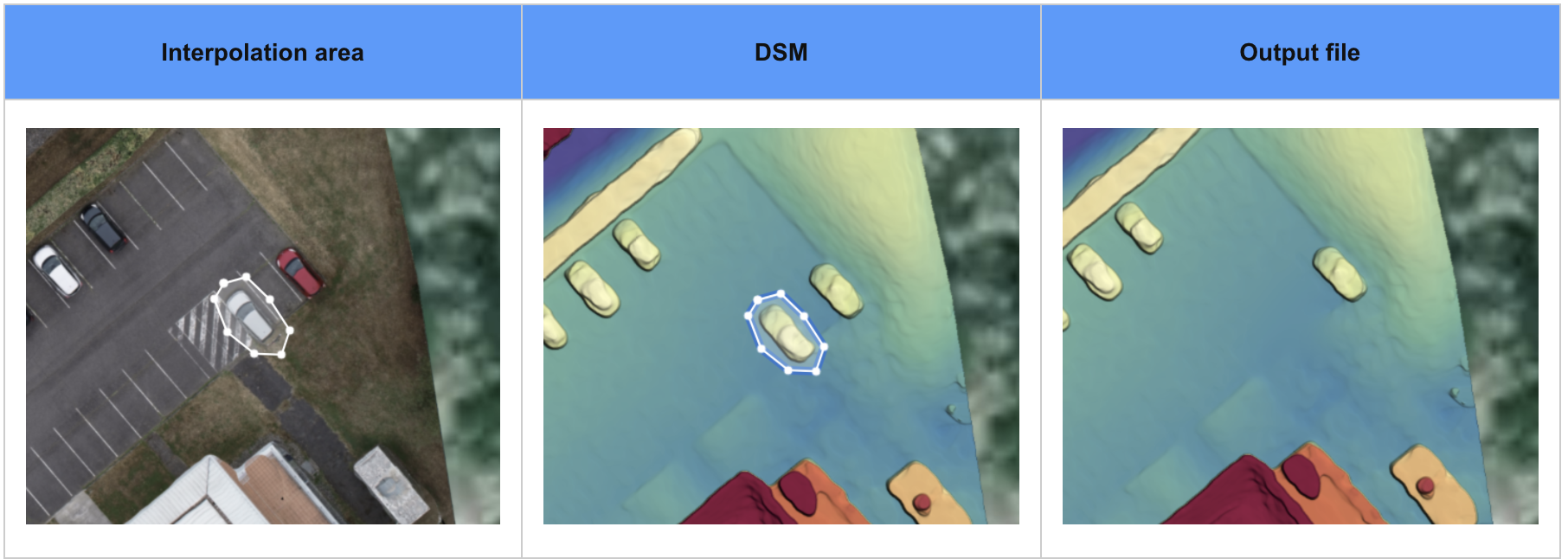
Similar to a Digital Surface Model (DSM), a Digital Terrain Model (DTM) is a topographic model of the bare Earth. A DTM excludes objects above ground level such as buildings, structures, cars, and trees. Simply highlight elevated objects that you wish to remove from the DSM, and the DTM analytic will automatically remove the associated elevation for these objects. A DTM can be used for a quarry or a mine site to remove unwanted ground objects from an area.
Example of a DTM (Output file) on a small area:
2. Inputs
Here are the mandatory inputs for this analytics:
- DSM (Digital Surface Model): Available after photogrammetry processing.
- Interpolation Area: vector file (DXF, KML, GEOJSON) that delimits the area/objects (trees, vehicles, or water bodies) that will be removed to generate the DTM.
The interpolation area can be drawn on Aeter with the polygon annotation tool and converted, see Field Boundaries Creation, or Create a New Vector Layer.
3. Workflow
3.1 DTM Generation
Step 1 - Open a Project in Aether, then select the appropriate Survey. The survey must contain a preliminary DSM (generated from the photogrammetry process in Aether, or imported from a third-party software) and one or multiple interpolation areas.
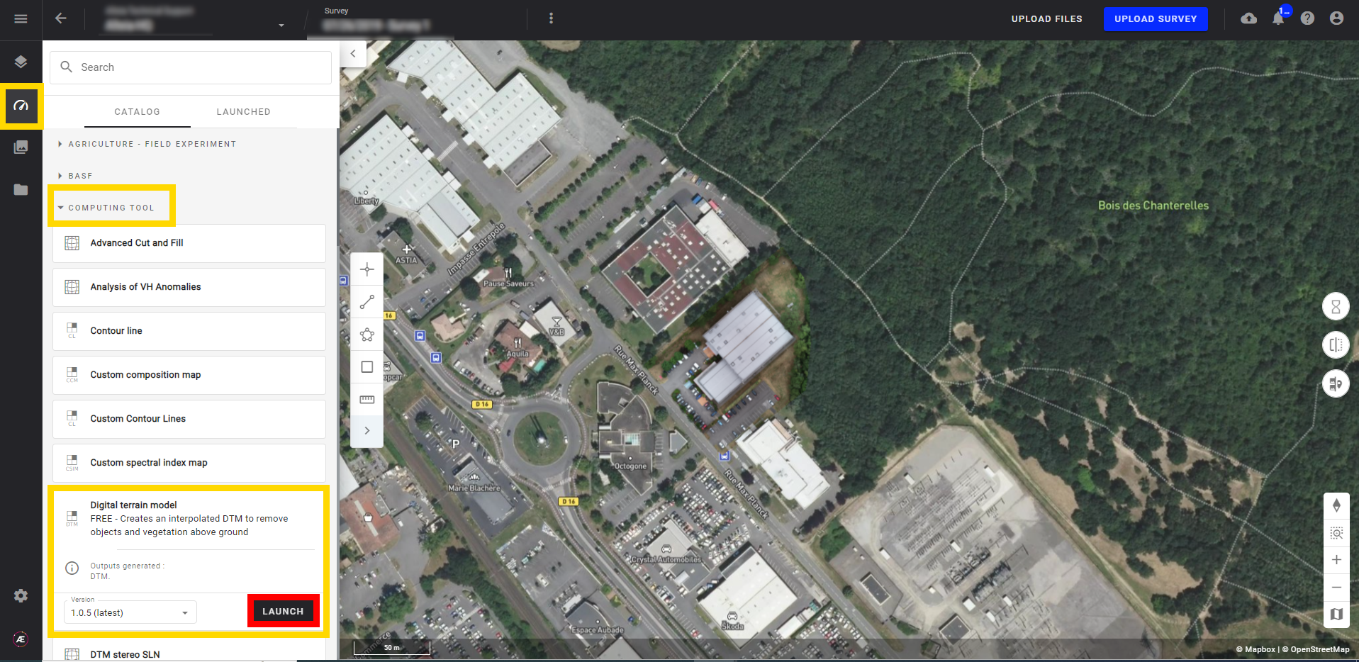
Step 2 - Go to the analytic catalog from the analytics button on the left menu, select "Digital terrain model", and click on "LAUNCH".
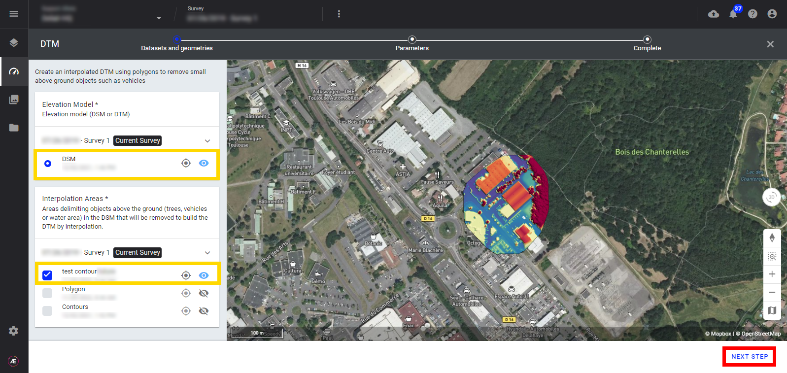
Step 3 - Select the DSM as a base layer and one or multiple Interpolation Areas, created previously as annotated polygons and converted to field boundaries.
Step 4 - Press the "NEXT STEP" button.
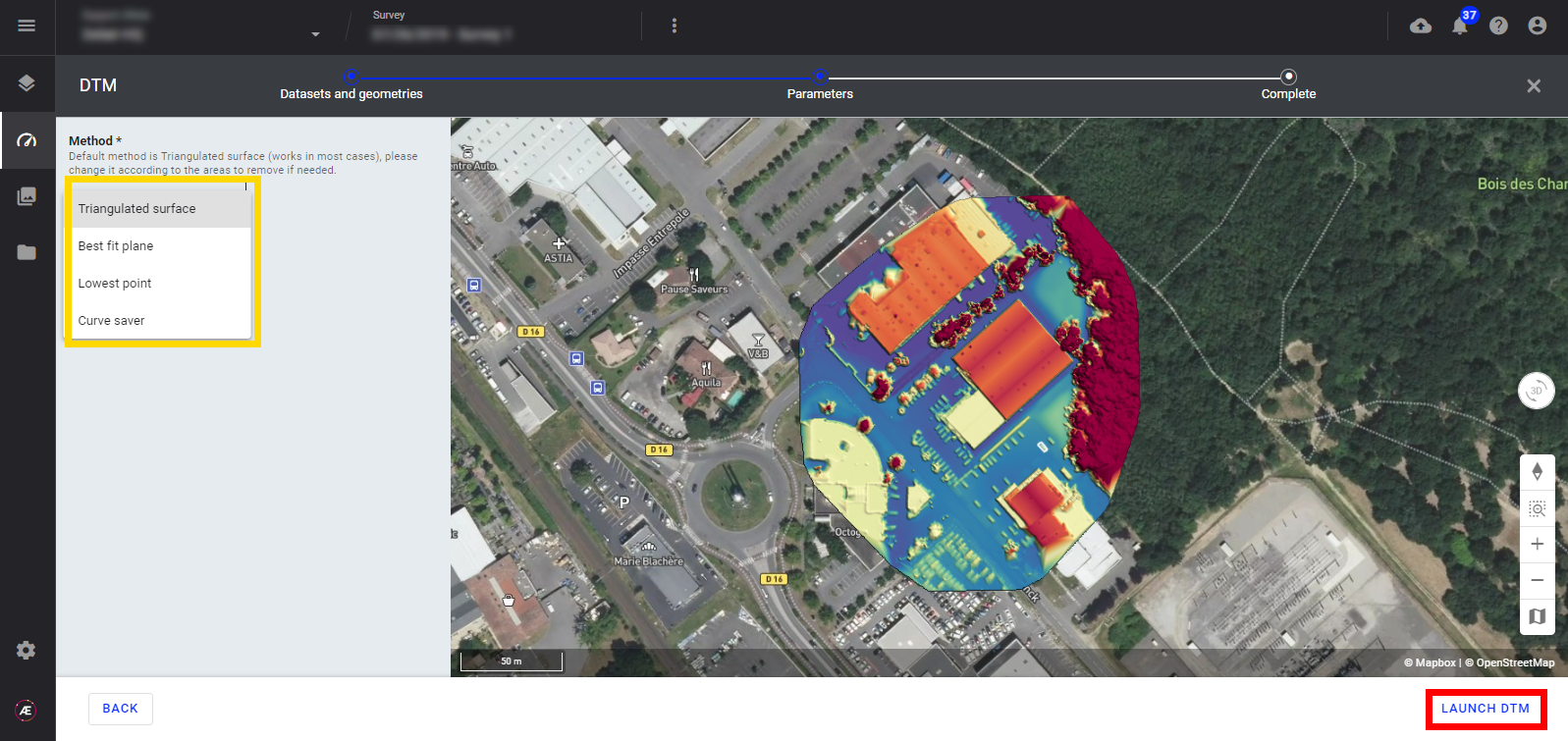
Step 5 - Now select the interpolation method and click on "LAUNCH DIGITAL TERRAIN MODEL":
- Triangulated surface (Default): Replace the areas marked out by the input contour with meshed surfaces. Each surface is computed by running a Delaunay triangulation of the input's contour points.
- Best fit plane: Replace the areas marked out by the input contour with the best fit plane.
- Lowest point: Replace the areas marked out by the input contour with a plane fitted over the input contour points.
- Curve Saver: Replace the areas marked out by the input contour with surfaces that preserve the surrounding curvature.
Note: It is useful to remove conveyors over stockpiles without distorting the shape of the stockpile.
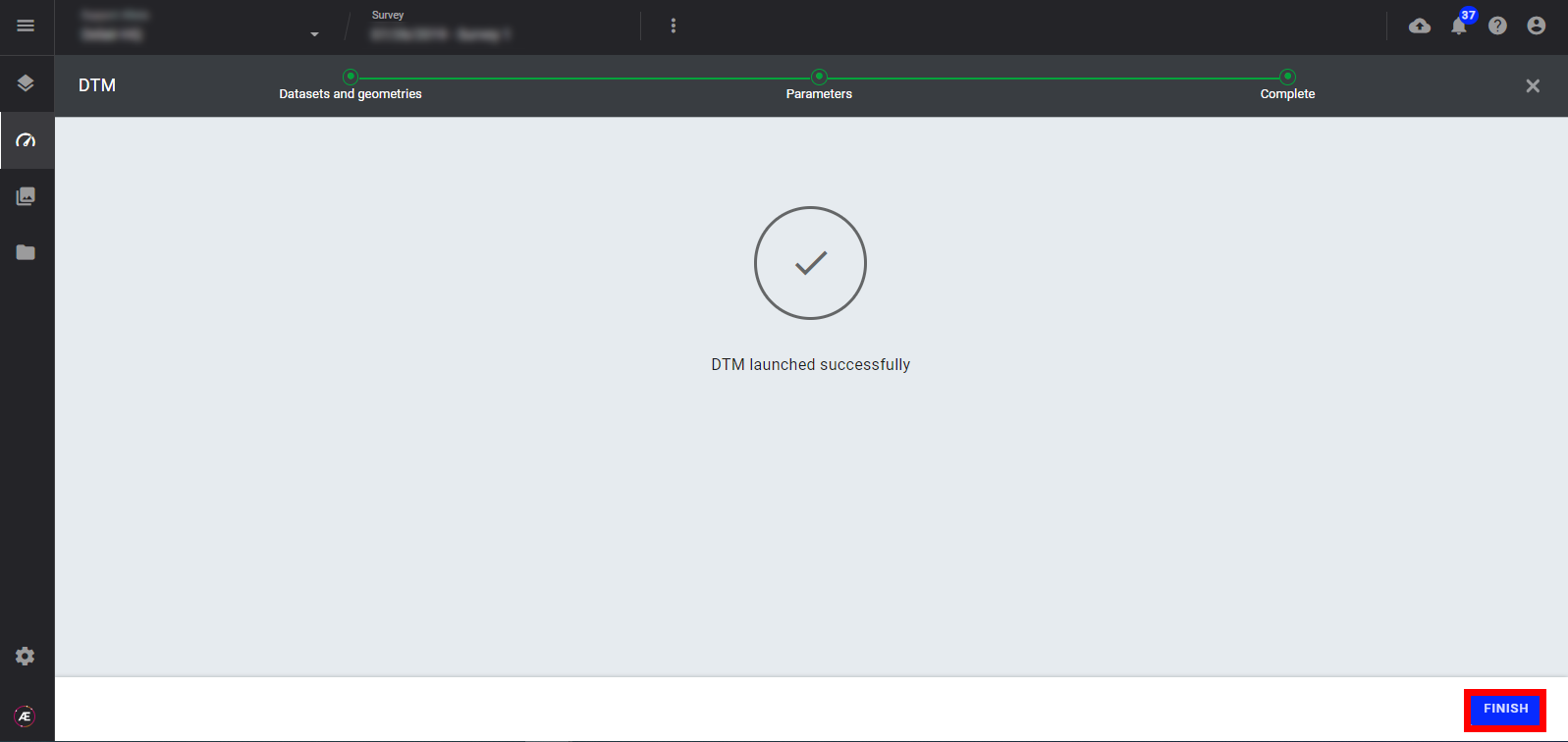
Step 6 - Click on "FINISH".
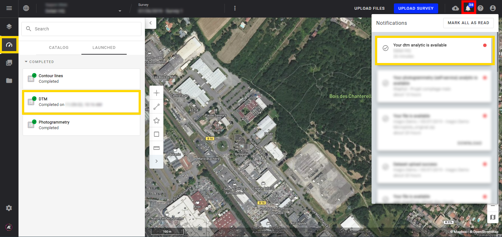
3.2 Progress & Completion Status
- Check the status anytime from the analytics LAUNCHED tab.
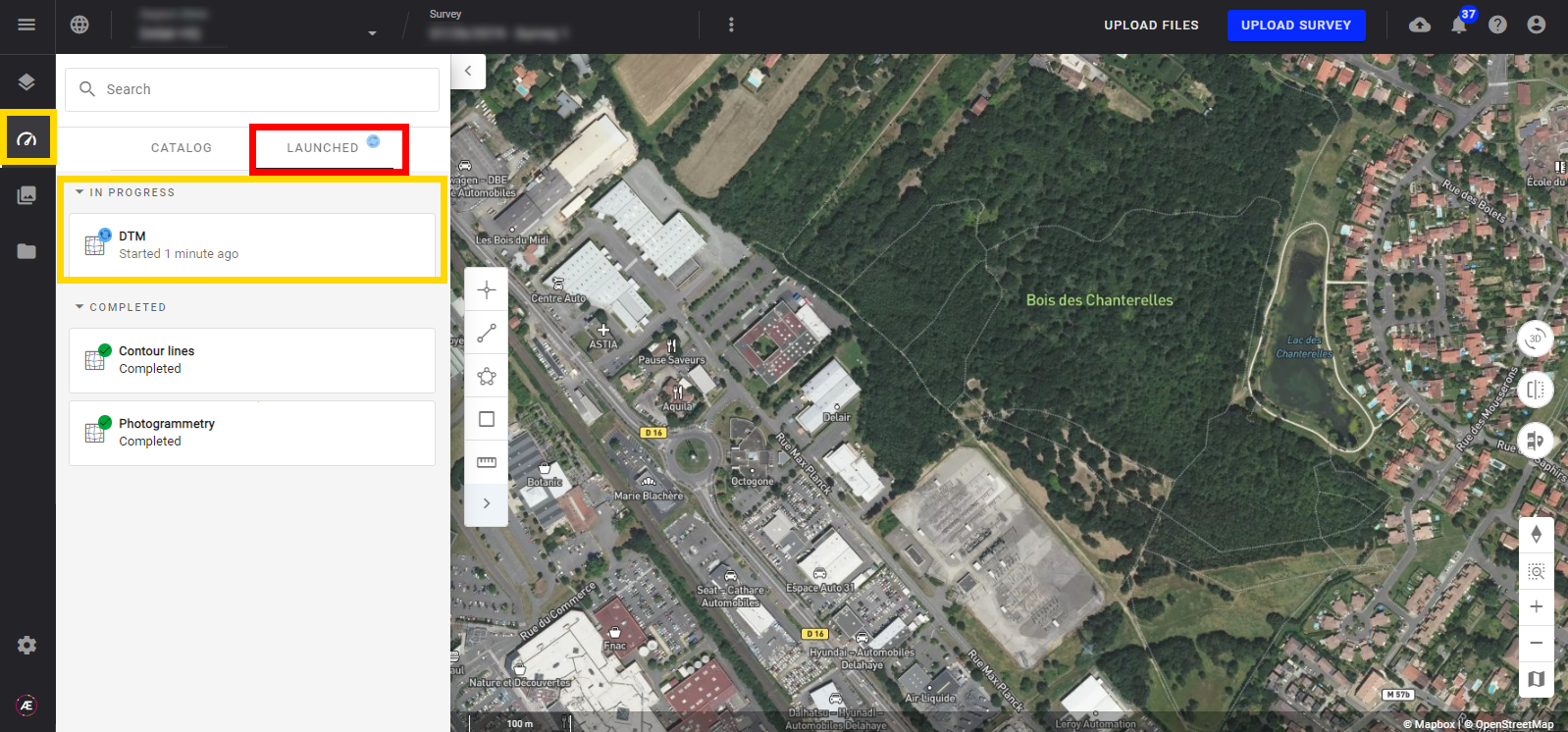
- A notification is sent to inform of the end of the treatment, see Notification Center.
4. Results
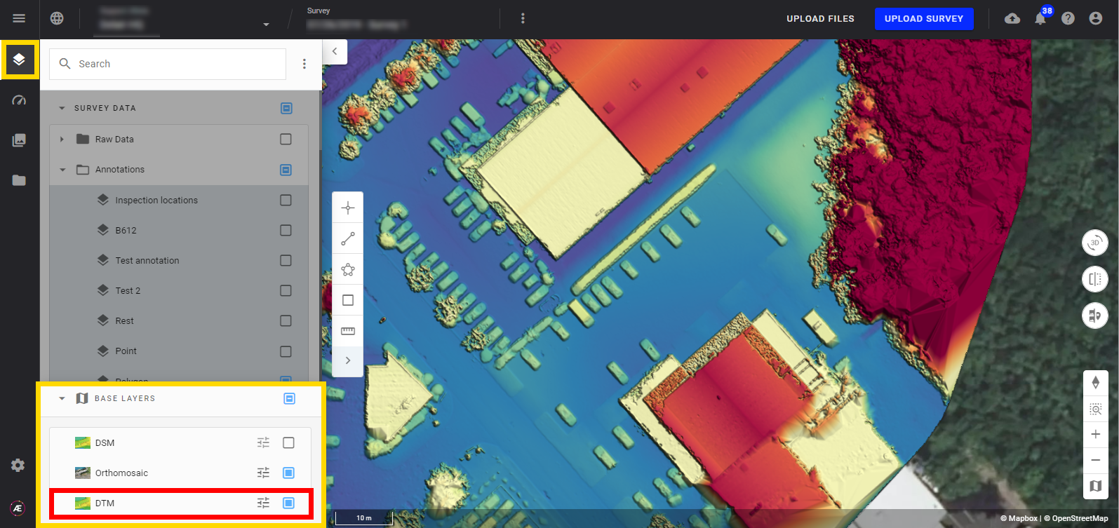
Exit the Analytic section and follow the steps below to view the generated DTM.
Step 1 - Go back to the Layers section, open the "BASE LAYERS" section, and select the DTM.
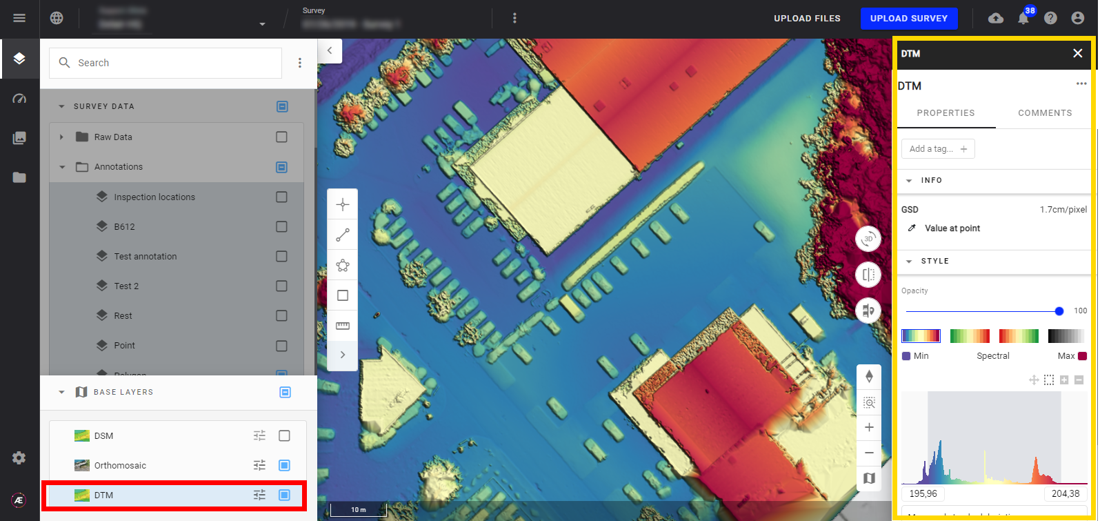
Step 2 - Clicking on the DTM will open the information panel, where you can view the DTM properties. Measure the elevation at any point of the map using the Value at point tool.
5. Deliverable
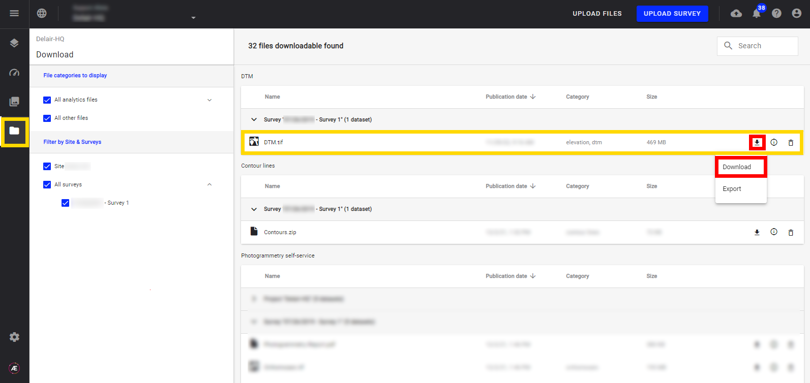
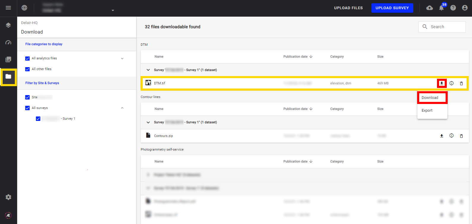
After generating the DTM, you can export the model for external use.
Go to the Downloads section and select the DTM file or use the "Search" function to download.